28
5.2 UTILIZATION
The machine must only be used by authorized personnel. Use by personnel who are not familiar with the
procedures specified in this manual could be dangerous.
The operation of the machine is as follows:
Vehicle positioning
When positioning the vehicle over the pads, pay attention to the following recommendations:
a) the total weight of the vehicle must not exceed 4000 kg
b) place the vehicle on the pads, making sure that it is aligned and centered with respect to the longitudinal axis of
the lift.
c) the maximum load of 4000 kg must be distributed on the four vertices of a rectangle having a transvers
e
di
mension of 1000 mm and a longitudinal dimension of 1800 mm. For lower transverse distance values and / or
longer longitudinal distance the lift capacity is reduced. In these cases or in other cases not covered by this
manual it is advisable to contact the manufacturer.
d) the use of accessories not authorized by the manufacturer to modify the support distances of the lifting pads is
forbidden.
e) The method of lifting the load must not present dangers and must observe the rule that requires stopping after
a
s
hort lift to check that the vehicle is correctly positioned and in a safe condition.
The Manufacturer disclaims any and whatever liability for damages to persons, animals or property
arising from non-compliance with the instructions given herewith and/or from an improper use of
the lift or any use other than specified in this manual.
T
o lift vehicle, proceed as follows:
• Check that the arms are turned in a way that will not hamper the vehicle access between the lift columns.
• Turn the arms and pull out the extensions bringing the pads to the points designed for lifting the vehicle as
indicated by the vehicle manufacturer.
W
ARNING:
Before lifting a vehicle, always check the load distribution with respect to the vehicle mass, strictly
complying with the LOAD DISTRIBUTION table (Fig. 3). Do not lift the vehicle in case the values found are
not within the limits given in the LOAD DISTRI-BUTION table.
Lifting of the vehicle
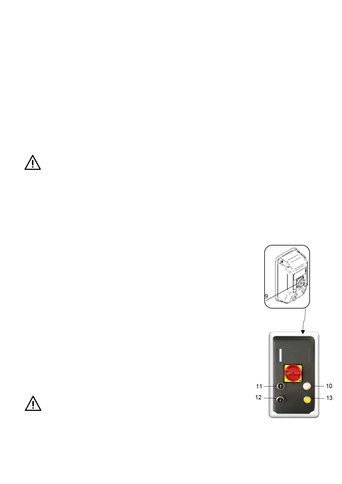
• Turn the emergency switch [9] clockwise and check that the power light [10] is on.
• Press the up button [11] and lift for about 30 cm, check that the support points hav
e
a c
orrect grip; if correct, continue the climb until the desired working height is
reached.
• Carefully check the stability of the load throughout the climb.
• In the event that there is a precarious stability of the vehicle or abnormal operatio
n
of
the lift itself, immediately stop the maneuver to climb, wait for the stabilization of
the load and proceed with small descents to the ground. Reposition the lo
ad
c
orrectly or proceed to stop the lift if the cause of the instability turns out to be of
a
technical nature.
Descent of the vehicle
Turn the emergency switch [9] clockwise and check that the power light [10] is on.。
P
ress the down button [12] ,the lifter will automatically rise a short distance .then
the lifter descent .
Release button [12]once the desired working height has been reached.
D
uring the entire descent, carefully check the stability of the load.
In the event that a precarious stability of the vehicle or abnormal operation of the lift is
found, immediately stop the maneuver, wait for the stabilization of the load
and proceed with small descents to the ground. Reposition the load correctly
or proceed to stop the lift if the cause of the instability turns out to be of a
technical nature.