Do you have a question about the Duplo DP-S850 and is the answer not in the manual?
Identifies the specific product series covered by the service manual.
Provides crucial safety warnings and guidelines for handling the equipment.
Explains the meaning and importance of safety symbols like WARNING and CAUTION.
Details environmental conditions and placement guidelines to avoid for safe and optimal operation.
Provides specific warnings and instructions related to the installation process of the machine.
Outlines essential safety precautions to be taken during maintenance and servicing operations.
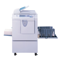
Identifies and illustrates the external parts of the machine for easy recognition.
Provides a detailed cross-sectional diagram of the machine's internal structure.
Details the functions and operation of each button and indicator on the control panel.
Describes the information displayed on the LCD panel and how to navigate it.
Details the function and circuit diagrams for slider limit sensors.
Explains the function of the CCD and lamp assembly, including circuit and specifications.
Details the sequence of operations for setting and feeding the master.
Explains the operation of platemaking and master feeding, including the role of the master clamp.
Explains the function, circuit, and sensitivity adjustment of the end mark sensor.
Describes the drum master sensor's function, circuit, and sensitivity adjustment.
Explains the function, circuit, and operation of the master feed clutch.
Explains the master clamp opening/closing section, including its operation.
Details the operation and structure of the master clamp open/close lever.
Illustrates the step-by-step operation of master attachment and detachment.
Shows the clamp opening/closing lever positions for B and C modes.
Details the printing position adjusting mechanism and how it's controlled.
Explains the operation of the paper feed roller and timing roller rotation.
Provides circuit diagrams for vertical registration sensors and motors.
Explains the double feed detection mechanism and its circuit.
Explains the paper sensor's function, circuits, and operation for detecting paper presence.
Details the function, circuit, and operation of the drum position 1 sensor.
Explains the function, circuit, and operation of the drum position 2 sensor.
Describes the drum removal button and its associated LED, including circuit details.
Explains the function, circuit, and operation of the JOG switch for drum rotation.
Details the control of the main motor, including rotation speed control via encoder sensor.
Explains press roller timing, printing area requirements, and adjustment of the printing area.
Details the function of the press roller sensor and its role in paper feeding detection.
Describes the contact pressure position sensing mechanism using center and encoder sensors.
Details the mechanical structure and operation of the paper stripper finger.
Describes the paper eject jam sensor, its function, and circuit.
Classifies and explains the detection timing for different types of paper jams.
Describes the drum section, ink control, and drum attachment detection.
Explains ink detection, its mechanism, and the "NO INK" display condition.
Provides circuit diagrams for ink roller, ink pump, and detection systems.
Describes the ink roller up/down mechanism for preventing ink insufficiency.
Illustrates the ink roller's standby, descent, and ascent operations.
Explains the ink pump's mechanical structure and operation.
Details the drum switch's function, circuit, and operation for detecting drum installation.
Describes the front cover switch's function, circuit, and operation.
Outlines the steps for removing the ink detection PCB unit, with reinstallation notes.
Provides instructions for removing the ink roller up/down motor, with reinstallation notes.
Provides a list of external parts and their removal procedures.
Explains the removal of main PCB, drive PCB, relay PCB, and power supply units.
Details the removal procedures for components within the Master Feed Section.
Details the removal of paper top detect, signal, and double feed detect sensors.
Covers adjustments for timing belt tension and thermal head position.
Covers spring attachment and timing belt tension adjustment for master ejection.
Covers timing belt tension adjustment and master clamp positioning.
Details the adjustment procedures for the double feed detection sensor (standard/heavyweight).
Details the adjustment procedures for the vertical registration sensors.
Explains how to adjust the drum's stop position for proper operation.
Details the adjustment procedure for the master attach position.
Provides a guide for troubleshooting common operational issues and error messages.
Lists error messages and their corresponding remarks, numbers, and page references.
Lists specific error items, symptoms, and corresponding page numbers for troubleshooting.
Provides troubleshooting steps when the lamp does not light up.
Details troubleshooting for the optical system's movement issues.
Troubleshooting steps for the "E001" error display.
Troubleshooting steps for the "E002" error display related to elevator motor.
Troubleshooting steps for the "E005" error display related to ink roller up/down motor.
Troubleshooting steps for the "E006" error display related to press motor.
Troubleshooting steps for the "E009" error display related to thermal head voltage.
Troubleshooting steps for the "E011" error display related to thermal head up/down motor.
Troubleshooting steps for the "E012" error display related to clamp motor.
Troubleshooting steps for the "E013" error display related to scanner stepping motor.
Troubleshooting steps for the "E015" error display related to vertical registration motor.
Troubleshooting steps for the "E016" error display related to horizontal registration motor.
Troubleshooting steps for the "E020" error display related to tape cluster cutter motor.
Troubleshooting steps for the "E021" error display related to communication with tape cluster.
Troubleshooting steps for master feed clutch malfunction.
Introduces the machine's self-diagnosis function and its error code display.
Lists code displays, their detection timing, causes, and page references.
Details detection timing for various error codes.
Lists the causes associated with specific error codes.
Details the display of error history from 1-6 and service call history.
| Type | Disc Duplicator |
|---|---|
| Model | DP-S850 |
| Number of Drives | 8 |
| Interface | USB 2.0 |
| Power Supply | AC 100-240V, 50/60Hz |
| Weight | 32 kg (70.5 lbs) |
| Maximum Read Speed (CD) | 48x |
| Maximum Write Speed (CD) | 48x |
| Maximum Read Speed (DVD) | 16x |
| Supported Disc Formats | CD-R, CD-RW, DVD±R, DVD±RW |
| Supported Operating Systems | Windows |