D-FL 200 / Rev. 6 7
______________________________________________________________________________________________________
Industrie Elektronik GmbH & Co KG
Temperature and absolute pressure measurements are required for converting the volumetric flow to
standard volumetric flow. Alternatively these quantities can be programmed into the evaluation unit as
constants. Two 4-20 mA inputs for absolute pressure and temperature measurements are provided in
the evaluation unit. Existing equipment can simply be looped in.
The ultrasonic sensors do not come into contact with the stack gas. In particular, the build-up of
condensate is prevented. The purge air system is specially designed for this and has a negligible effect
on the ultrasonic signal.
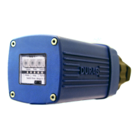
The transducers are exclusively supplied with auxiliary power from the evaluation unit. The
piezoelectric ultrasonic sensors are ruggedly built and are designed to withstand environmental
conditions.
3.1. Evaluation Unit D-FL 200-10
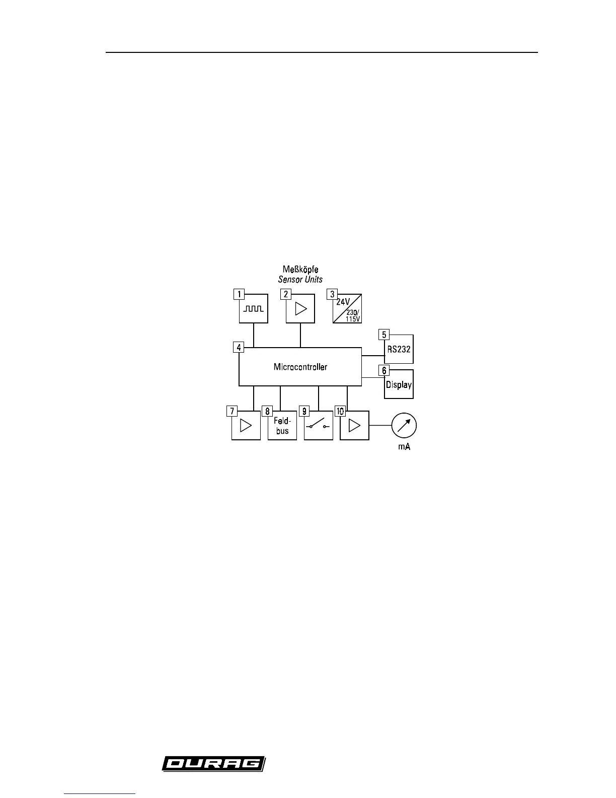
Two or (optional) four transducers may be connected to the evaluation unit. The block diagram below
depicts the operations of the unit.
(Fig. 6) Basic diagram of the microprocessor unit
1. Drive sensors
2. Sensor signal amplification
3. Auxiliary power for the transducers
4. Algorithms for assessment of measured values
5. RS232 interface
6. Display output function
7. mA inputs
8. Field bus communications interface (optional)
9. Limit value and state contacts
10. mA outputs



 To Next Page