D-FL 200 / Rev. 6 3
______________________________________________________________________________________________________
Industrie Elektronik GmbH & Co KG
Volumetric flow may be obtained using the following formula:
QkAv=⋅⋅
Equation 6
with: K Correction factor
A Stack diameter
Since each stack develops its own particular velocity distribution, the mean velocity is determined for
calculation of the volumetric flow. If the flow were completely laminar, a single spot measurement
would suffice. The acoustic impulse method enables a cross-sectional measurement to be made over
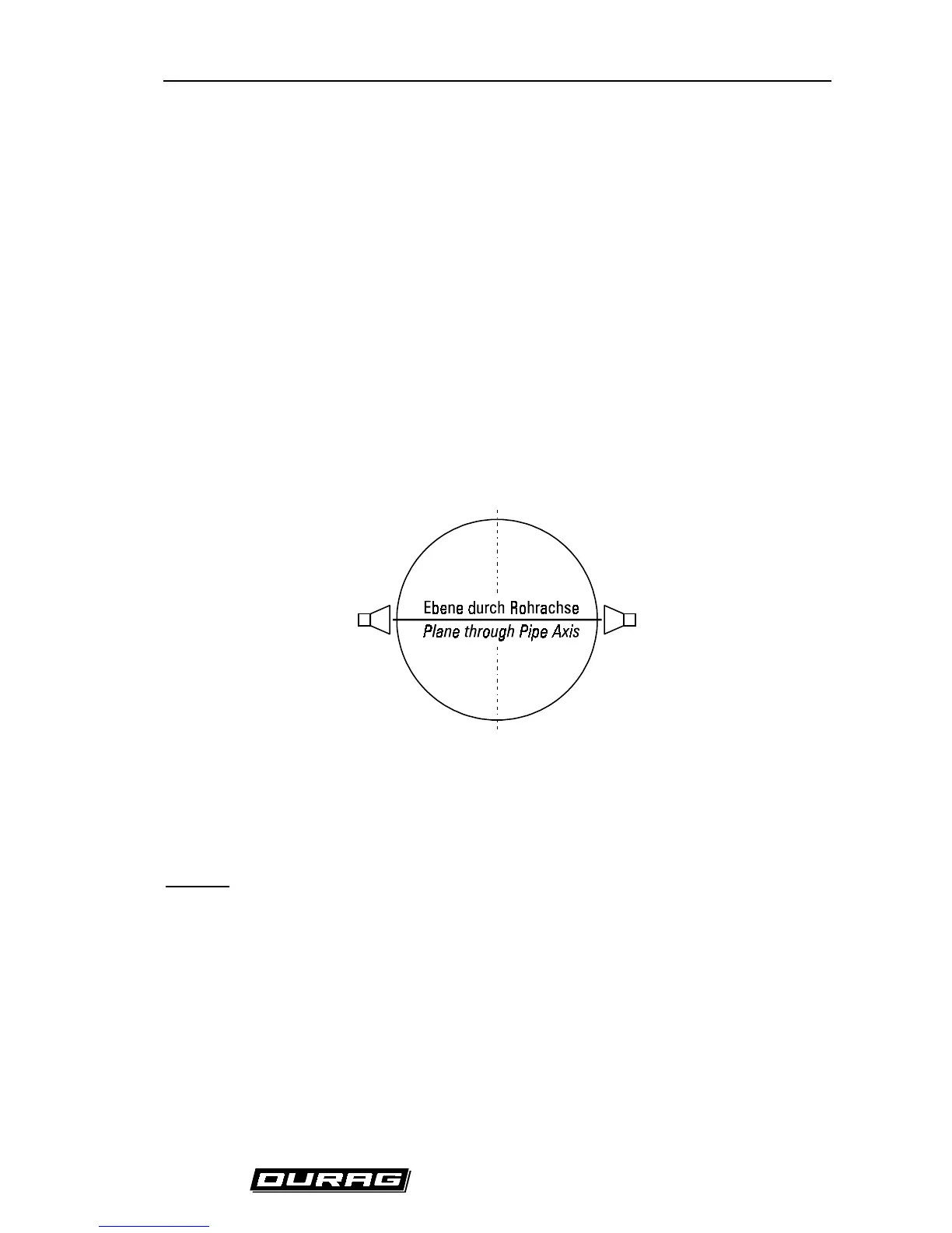
the entire diameter of the stack. If the ultrasonic sensors are arranged in a plane through a pipe axis,
as shown in
(Fig. 2) Plane through the pipe axis (standard)
, the measured velocity must be weighted
according to the geometry of the pipe.
(Fig. 2) Plane through the pipe axis (standard)
If flow velocity lies in the lower range, the correction factor is 0.75 for cylindrical stacks and 0.66 for
square stacks. If it is technically feasible to do so, a calibration should be performed in such an
installation.
Optional:
An alternative installation is one in which the ultrasonic transducers are installed in one or two planes
which do not run through the pipe axis. This arrangement is shown in
(Fig. 4) Measurement
independent of the flow profile (optional).
This setup is advantageous since the influence of the flow
profile on the measured result is minimized. This is shown schematically in
(Fig. 3) Consideration of
the flow profiles
. The measuring planes must lie in zones which intersect the variable velocity curves.