D-FL 200 / Rev. 6 24
______________________________________________________________________________________________________
Industrie Elektronik GmbH & Co KG
As an option temperature and pressure transmitters can be used. This is shown in
5.1. Electrical
Connection of the D-FL200-10 Evaluation Unit, (Fig. 16) Terminal strip on the
housing
page
14.
The
measuring resistors of these inputs are 100
. The maximum load of the transmitter should be taken
into account.
On the output side there are a mA-output for standard flow, a mA-output for velocity and three state
relays "ERROR“, "Maintenance“ and "Limit value“ available. On that outputs a strip chart recorders or
an "Emissions Evaluator" (for example DMS 285 or DMS 500) can be connected.
If there is no ‘ERROR’ the relay is in operation. If a fault occurs this relay contact is switched to ‘OFF’.
That includes, if there is a power fail this state relay will indicate an error too.
9.5. Start up of the evaluation unit D-FL 200-10
The system is programmed according to the data of the stack (see section 16. Measuring Point
Questionnaire
, page 40
).
Before appropriation you should check weather the data in the 'evaluation Unit' and the data in the
parameterisation sheet of the 'Customer Specific Calculations' are equal. Make sure that the
temperature and pressure measuring is set in the right way (internal/external).
If the data has changed the new parameters can be introduced as described in section
8. Operating
the D-FL 200-10 Evaluation Unit, page 17
. For the set up of the system the programmed measuring
path length is the most important parameter. If the programmed length is extremely different from the
real length, the system looks at the wrong time period for the transmitted signal (tolerance is about
2m).
If the installation and the parameterisation are finished, the verification of the ultrasonic signals can be
performed. This can either be done with the program D-FL200COM and a Notebook or PC where the
signal is directly shown.
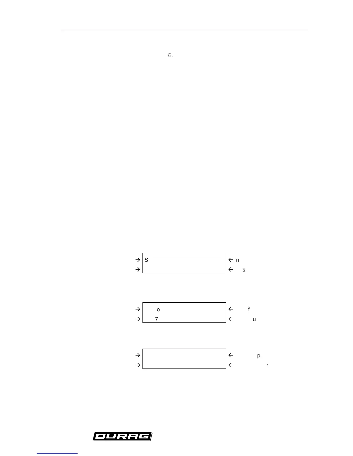
The second possibility is to use the display output of the D-FL 200-10. Press at first the "MOD“-key and
afterwards the "+“-key until the display shows "Sensor A“. In that position the amplitude of the received
signal is shown.
Indication of the Sensor
Æ
Sensor A 1734
Å
Index position in Array
Signal amplitude
Æ
87 5.
Å
Noise number
-> 10 seconds later the display shows another output:
Indication of the Sensor
Æ
Sensor A 0.320
Å
Amplification number
Signal amplitude
Æ
87 5.
Å
Noise number
-> 8 seconds later a new output appears.
Indication of the Sensor
Æ
Sensor A 0.00830
Å
Transmit power number
Signal amplitude
Æ
87 5.
Å
Noise number
-> 8 seconds later the original display output appears again, a. s. o.
If now the "STO“-key is pressed and the red LED changes to "ON", the automatic amplification control
is launched. The change of the amplification appears automatically in the display.
 Loading...