D-FL 200 / Rev. 6 10
______________________________________________________________________________________________________
Industrie Elektronik GmbH & Co KG
Caution!
The following must be observed during the electrical installation of the
D-FL 200:
• The installation may be done only by a skilled worker.
• Before performing any work on the system, it must be disconnected from the power supply.
• The power supply and frequency has to correspond with the information shown on the nameplate.
• Connections must be made as shown on the wiring diagram on the cover of the terminal strip.
• The grounded lead must be connected to the ground terminal.
• The motor safety switch (not included) must be set to the rated current of the motor.
• The direction of rotation of the motor must be checked (Arrow on the cover).
• Ensure a separate power supply for the purge air system, because the purge air has to blow all
the time.
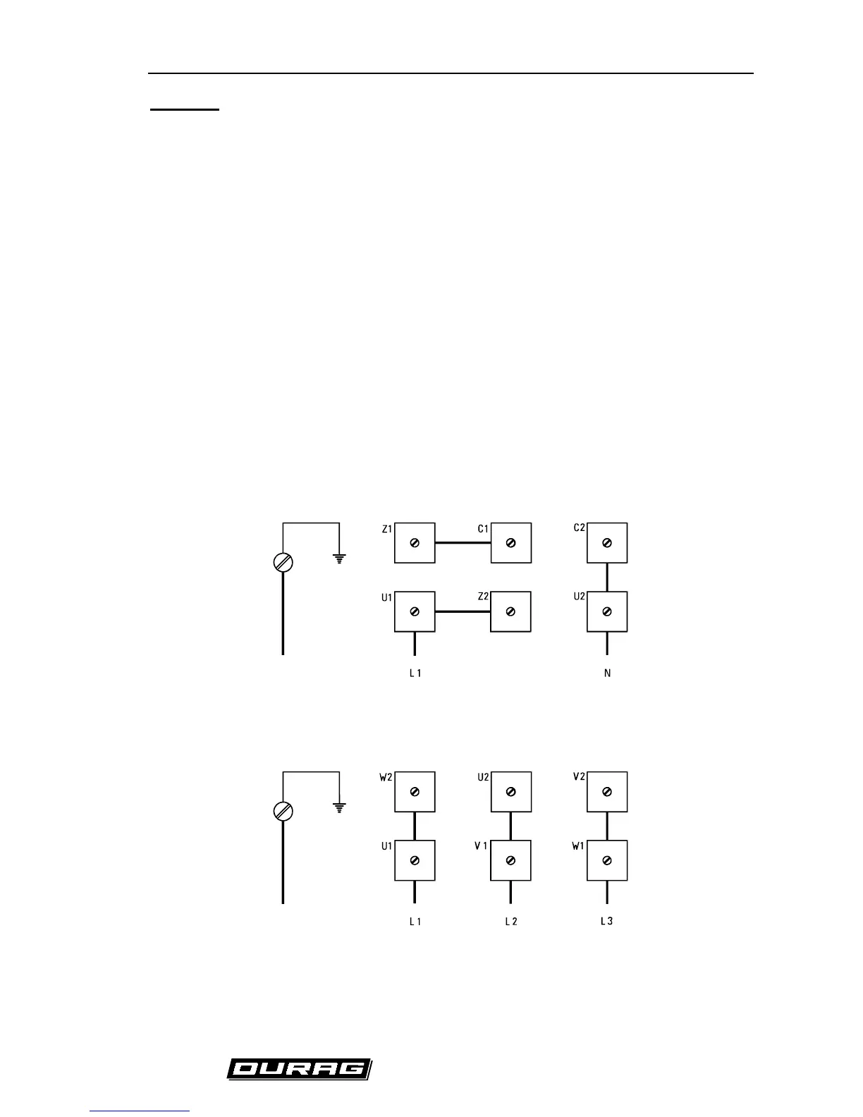
Use the wiring diagram as shown in
(Fig. 10) Electrical connection of the purge air system
if your
power supply is single phase. In the case of using three-phase power supply you must connect your
motor according to
(Fig. 11) Electrical connection 3-phase power supply 230V
and
(Fig. 12) Electrical
connection 3-phase power supply 400V.
Use
Fig. 11
if you supply with 200V - 240V. If you supply with
345V - 415V than connect the motor according to
Fig. 12.
Erde
Ground
(Fig. 10) Electrical connection of the purge air system
Erde
Ground
(Fig. 11) Electrical connection 3-phase power supply 230V
 Loading...