14 15
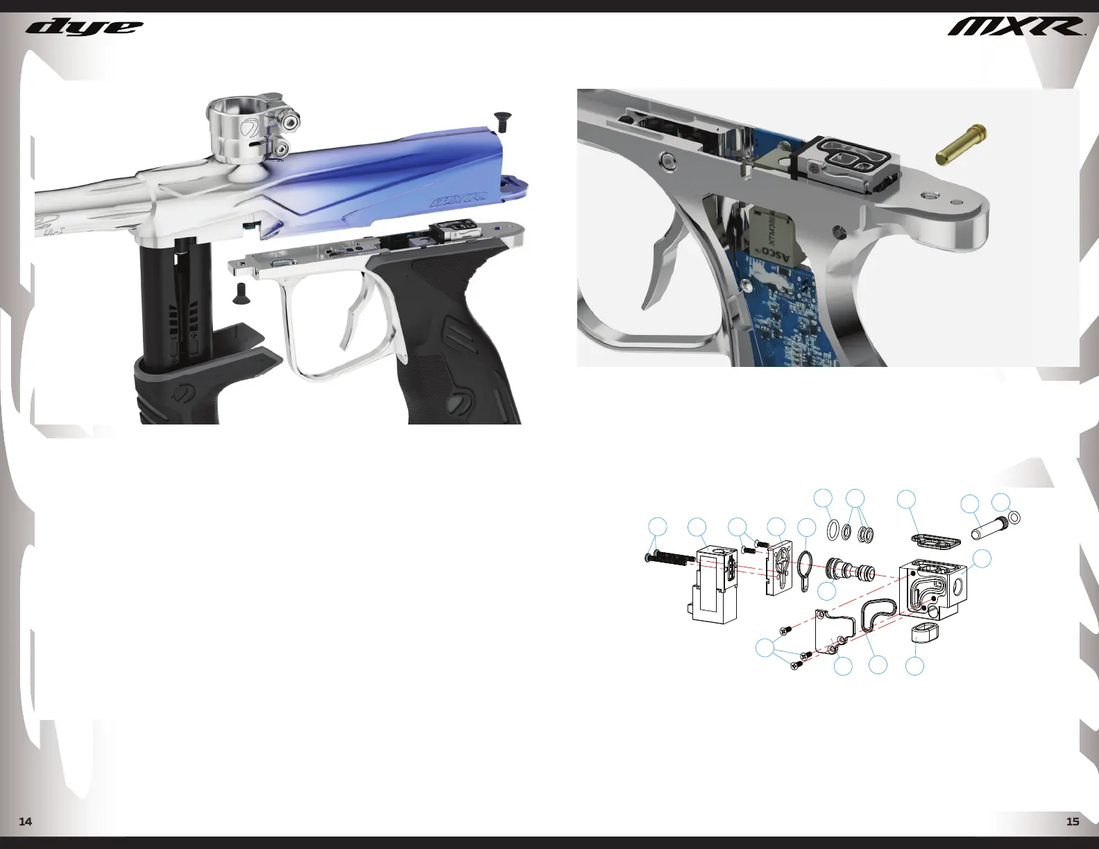
GRIP FRAME
If there is ever a reason to remove the UL frame from the MXR body make
sure to follow these steps.
• Remove the front grip to expose the front mounting screw.
• Remove the bolt kit to expose the rear mounting screw.
• Use a 3/32” (Red) allen wrench and remove both front and rear mounting
screws.
The MXR utilizes a positive force connector to link the body and frame
electrical components together. There are no wires to disconnect when
removing the frame from the body.
NOTE: BE SURE THAT THE FRAME AND TRIGGER ASSEMBLY ARE KEPT
CLEAN. IF THERE IS EXCESS DIRT OR PAINT BUILD UP AROUND THE
TRIGGER, THE TRIGGER WILL NO LONGER MOVE FREELY. IN ADDITION,
PAINT AND DIRT CAN CAUSE THE MICRO SWITCH TO NOT FUNCTION
PROPERLY OR FAIL.
REMOVING ULTRALITE FRAME
SOLENOID
To access the solenoid assembly, remove the frame from the body. See
frame removal instructions. Once frame is separated from body press the
brass solenoid retaining pin out and unplug the pilot lead wire from the
main circuit board. The solenoid assembly can now be pulled up and out of
the top of the frame.
REMOVING SOLENOID
PARTS LIST
6 - O-ring 1*3, N70
36 - Solenoid 3v Pilot(L60mm)
37 - Gen 2 Solenoid Body
38 - Gen 2 Solenoid Body Gasket
39 - Gen 2 Solenoid Sub Manifold
40 - Gen 2 Solenoid Sub Manifold Gasket
41 - Gen 2 Solenoid Side Plate
SOLENOID COMPONENTS
47
36
46
39
44
45
38
40
49
6
46
43
41
42
48
37
42 - Gen 2 Solenoid Side Plate Gasket
43 - Gen 2 Solenoid Piston
44 - 1x6mm N70 O-ring
45 - 3*6*0.8mm Solenoid N70 O-ring
46 - M 1.6*5(PO.35)Phillips Head Screw
47 - M 1.7.*16 | Head Screw
48 - Gen 2 Lower Solenoid Gasket
49 - Gen 2 Solenoid Retaining Pin
DYEPAINTBALL.COMDYEPAINTBALL.COM