32 CA 251/301 M251EN2
ELECTRICAL SYSTEM
Fuses
The machine is equipped with a 12 volt electrical
system and an alternator.
Connect the battery to the correct polarity.
Negative to ground. The cable between the
alternator and battery must not be
disconnected when the engine is running.
Before carrying out any electric welding on the
machine, disconnect the battery grounding
cable and then all terminals to the alternator.
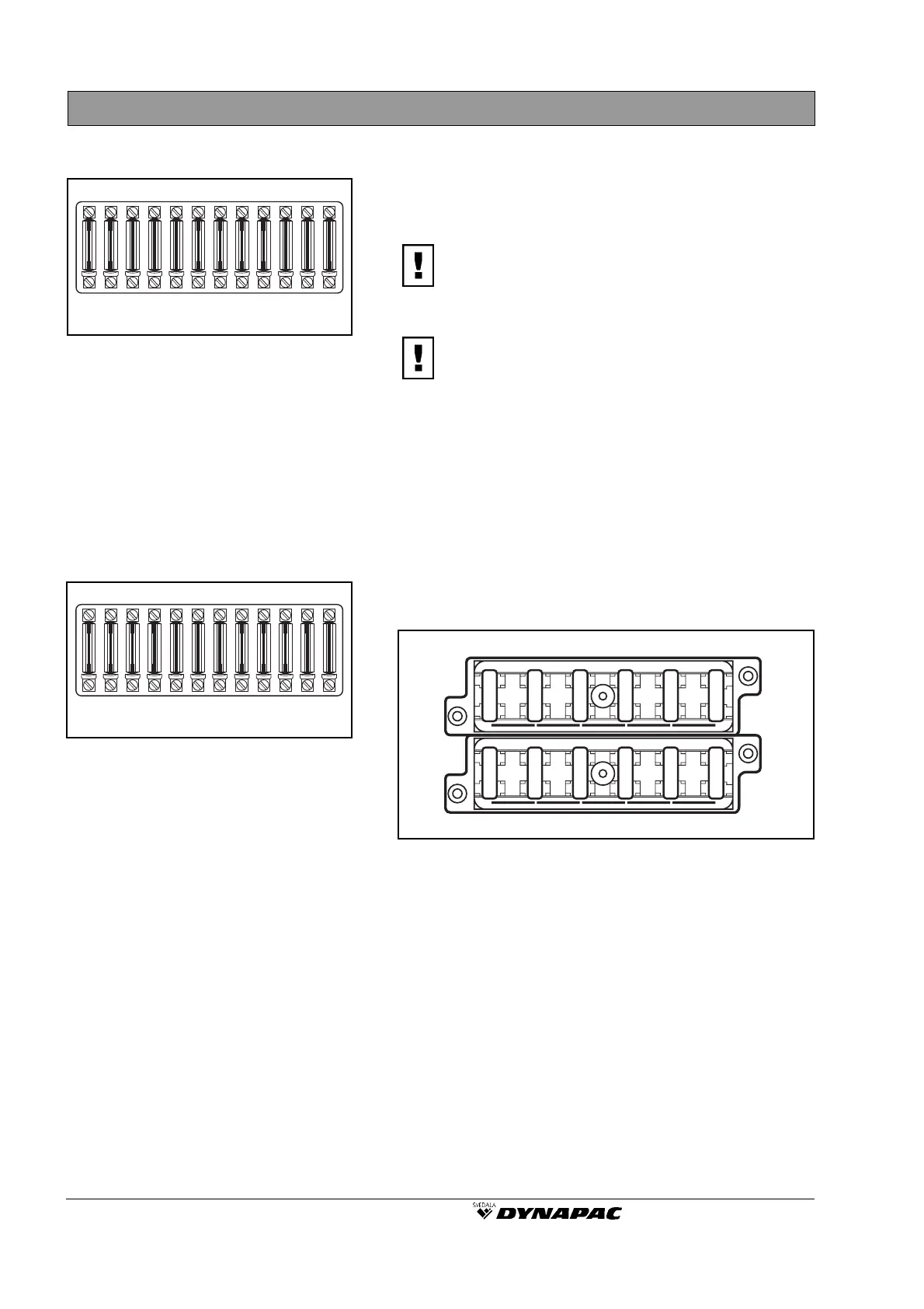
The electrical regulating and control system is
protected against overload by 8 A fuses, which are
located in fuse boxes on the steering column, see
maintenance diagram.
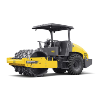
The lower fuse box is only fitted on rollers that are
equipped with driving lights, direction indicators and
rear working lights.
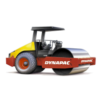
Fig. 58 illustrates the fuse boxes that are fitted in the
cab, ie, in cases where this is relevant (optional).
Fig. 58 Fuse box in cab (optional)
10A 1. Front working lights
10A 2. Rear working lights
3A 3. Front spraying
15A 4. Fan
15A 5. Front wiper
15A 6. Rear wiper
3A 7. Interior lighting, Radio
7.5A 8. Air conditioner
9. -
10. -
3A 11. Hazard beacon
25A 12. Cab heater
Fig. 57 Lower fuse box (optional)
13. Working lights, rear
14. Parking lights, left
15. Parking lights, right
16. Direction indicator/left
17. Direction indicator/right
18. Low beam, left
19. Low beam, right
20. High beam, left
21. High beam, right
22. Brake lights, right
23. Brake lights, left
24. -
Fig. 56 Fuse boxes
1. Vibration control
2. Instruments
3. Horn/V-belt monitor, Deutz
4. Stop solenoid, Cummins
5. Hazard beacon
6. -
7. Brake valve
8. Gear selector
9. Sprinkler (CA 251A)
10. -
11. -
12. Driving lights (optional equipment)
CAUTION
CAUTION
123456789101112
7
8 9
10
11
12
1
2 3 4
5
6
13 14 15 16 17 18 19 20 21 22 23 24