22
CC 102/C/122/C/132/142/C O102EN3
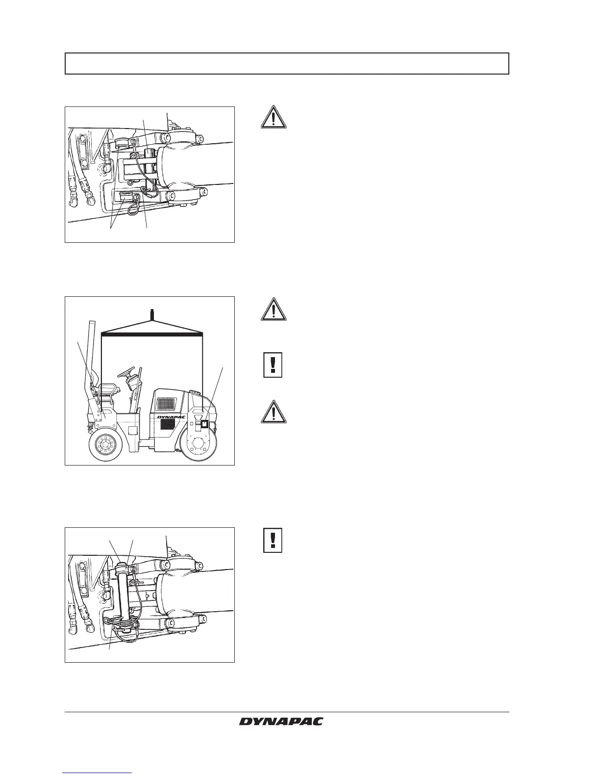
Locking the articulation joint
3 2
Fig. 30 Left side of articulation
1. Locking bar
2. Locking pin
3. Holder
1
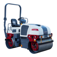
Fig. 32 Left side of articulation
1. Locking bar
2. Locking pin
3. Holder
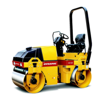
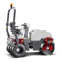
Fig. 31 Lifting the roller
1. Machine data plate (rear plate
on left side)
Weight: see machine data plate
on the roller
1
1
13
2
Releasing the articulation joint
Remember to restore the locking bar (1) to its
holder before driving again.
Before lifting the roller, the articulation
must be locked to prevent inadvertent
turning.
Turn the steering wheel so that the machine is set for
driving straight forward. Push the reserve/parking
brake knob.
Then pull down the bright galvanized locking bar (1)
from its holder (3), and insert it from below into the hole
in the lower articulation mount, push the bar through
until its upper end is visible in the hole of the upper
articulation mount.
Then secure the bar stud in position with the locking pin
(2).
INSTRUCTIONS FOR LIFTING
The maximum weight of the machine is
noted on the hoisting plate (1). See also
technical specifications in the maintenance
instructions.
Lifting gear, such as chains, steel wires,
straps, and lifting hooks must be dimensioned
in conformance with current regulations.
Keep well clear of the hoisted machine!
Make sure that hoisting hooks are securely
anchored.