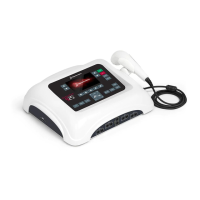
Dynatron® 850plus & 550plus
Installation & Features
12
Microcurrent Selections:
24. MICRO: Press this key to begin setup of a microcurrent treatment. This key is also used
to turn the conductance tone off and on after a microcurrent treatment is started. When
MICRO is selected, Channel 1 is automatically selected for the default electrodes
treatment and the LED for that channel is lighted. For a microcurrent treatment setup
with electrodes, connect a patient lead wire to Channel 1 output jack. For a microcurrent
probes treatment, press the channel toggle key (CH) to select the MICRO channel
selection (Channel 1 LED will become yellow and MICRO will become green to indicate
the probes option is selected). Connect the microcurrent probe to the microcurrent output
jack on the left side panel of the device.
NOTE: Channel 1 is committed to the microcurrent output during a probes treatment as
well as during a treatment with electrodes, and is not available for use by any other
modality while any microcurrent treatment is in progress.
MICROCURRENT POLARITY: To select or change the polarity of a microcurrent
treatment, use the MICRO key together with the FUNCTION key. Press and continue
holding the FUNCTION key while pressing the MICRO key one or more times to select
positive only (the “+” LED is lighted), negative polarity only (the “-” LED is lighted), or
dual polarity (both LEDs are lighted).
25. OUTPUT JACK CHANNELS 1 and 2: These are the output jacks for delivering
interferential, premodulated, Russian, biphasic, and microcurrent treatments. Consult
treatment instructions later in this manual for appropriate channels and treatment setup
for each modality.
26. HIGH VOLT OUTPUT JACK HV. This is the output jack for delivering high volt
treatments. Consult treatment instructions later in this manual for high volt treatment
setup.
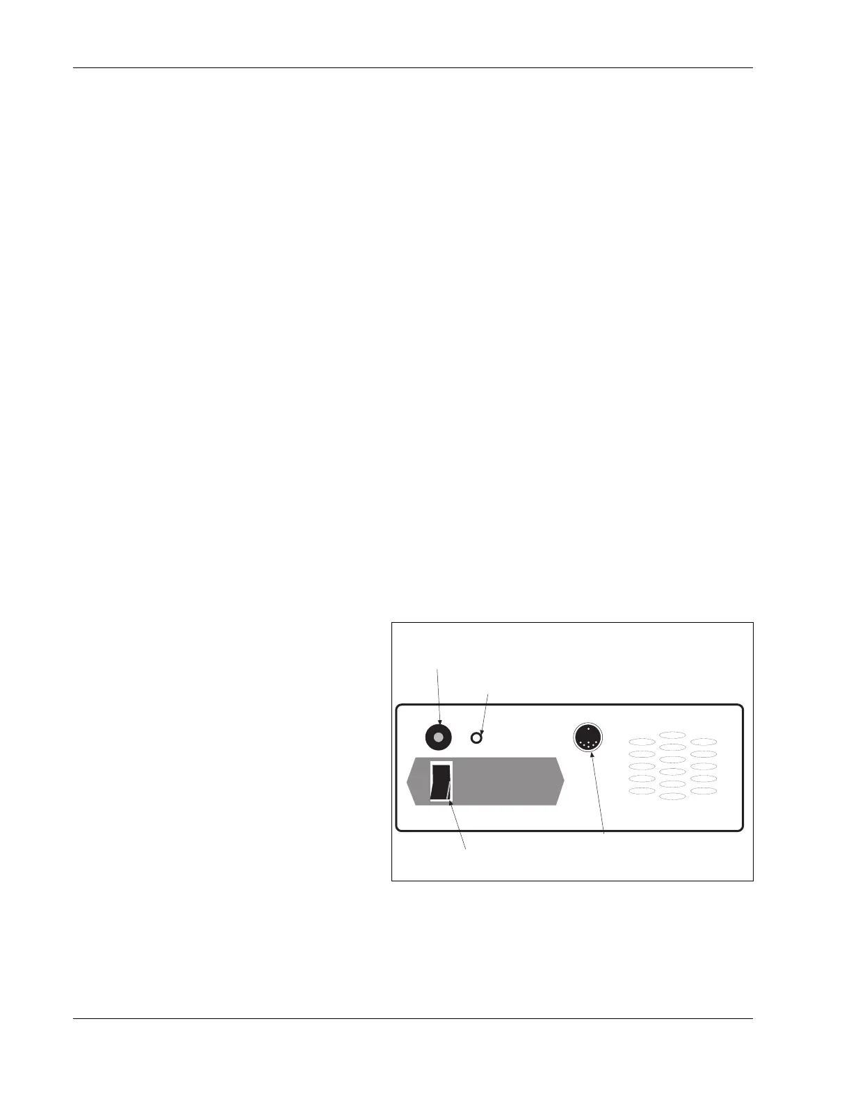
Dynatron 850plus and
550plus Back Panel:
27. POWER ON/OFF
SWITCH: Located on the
back of the unit this switch
is labeled “1” and “0”. Set
the switch to “1” for ON;
set the switch to “0” for
OFF.
28. STIM INPUT JACK FOR
COMBINATION
TREATMENTS: The special
lead wire for combination
treatments is plugged into this
jack for a combination
treatment setup providing stim output through the ultrasound head. The special lead wire is
also plugged into the jack on the front of the device which has been selected for the specific
combo treatment. See combination treatment instructions later in this manual for detailed
information regarding combination treatment setup.
1
0
Batt. Input
28. Electrical Stim to Ultrasound
Input Jack (only on D850plus)
29. Jack for Optional Battery Pack
27. Power On/Off Switch
30. Patient Remote Stop Jack
Dynatron 550plus and 850plus Back Panel