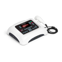
Dynatron® 850plus & 550plus
Installation & Features
14
IFC and Premod
• Target/Sweep (IFC only)
• High/Low Frequency Ranges
Russian and Biphasic Stim
• Treatment mode
• Contraction/Rest cycle
• Ramp Time
High Volt Stim
• Contraction/Rest cycle
• Ramp Time
• Polarity
• High/Low Pulse Rate Ranges
Microcurrent
• Microcurrent Polarity
• Channel toggle to select Micro or Channel 1 (during setup only)
All Modalities
• Time/Frequency/Rate/Width
• Channel Toggle (to view individual channels one at a time while treatments are in
progress
Ultrasound (Dynatron 850plus only)
• Ultrasound Frequency
• Ultrasound Duty Cycle
High Volt Intensity Display
High volt intensity is displayed in volts
Microcurrent Intensity Display
Microcurrent intensity is displayed in
microamperes
Stim Intensity Display
The intensity display is intended as an
incremental value only for the convenience
of the practitioner.
Increasing the intensity does increase
current delivery. However, intensity and
current are not a 1:1 comparison. Actual
current delivered to the patient depends
upon the intensity setting and the current
density (affected by the size and
condition of the electrodes).
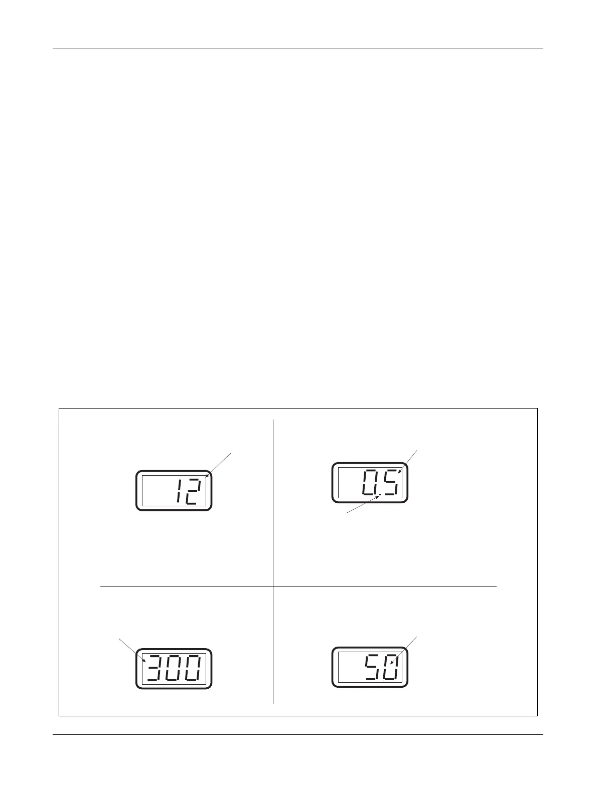
A blinking decimal indicates the power is displayed
as WATTS. A steady (non-blinking) decimal
indicates WATTS/cm2. Pressing and holding the
PAUSE key changes the display from WATTS to
W/cm2 or reverse.
Ultrasound power is displayed, with the value
shown either in WATTS or W/cm2.
Ultrasound Power Display
POWER-INTENSITY
POWER-INTENSITY
POWER-INTENSITY
POWER-INTENSITY
Examples of Power-Intensity displays for the Dynatron 850plus and 550plus.