Powerbox Pro series User Manual
20
2) Inverter Connection
When the system is used independently:
Note: Before installation, please confirm whether the DIP switch mode of the master
module in powerbox Pro is correct according to use’s inverter communication
specification. For specific DIP operation methods, please refer to “3.2.4 Battery module
DIP switch definition and description.” Except for the inverter specified by the customer's
special requirements, the factory default DIP switch mode of master module is DIP
Switch mode 1 (ADD: 0010). If the inverter is equipped with other DIP switch mode, open
the front panel and Set DIP switch mode of the master module to the correct mode.
Before opening the cover to operate, you must contact DYNESS and inform the ID of the
product. DYNESS records this battery ID and authorizes the opening operation. Except
changing the DIP switch mode, no other operations can be done.
The battery is connected to the inverter, and it is required to use the dedicated power cable
and communication cable (as accessories shipped with the cargo, the standard
communication cable is a standard network cable. The applicable inverter is marked on the
label of the network cable. If the inverter used by the customer is not covered by the
standard communication cable, please contact DYNESS for the correct PIN Sequence) as
follows:
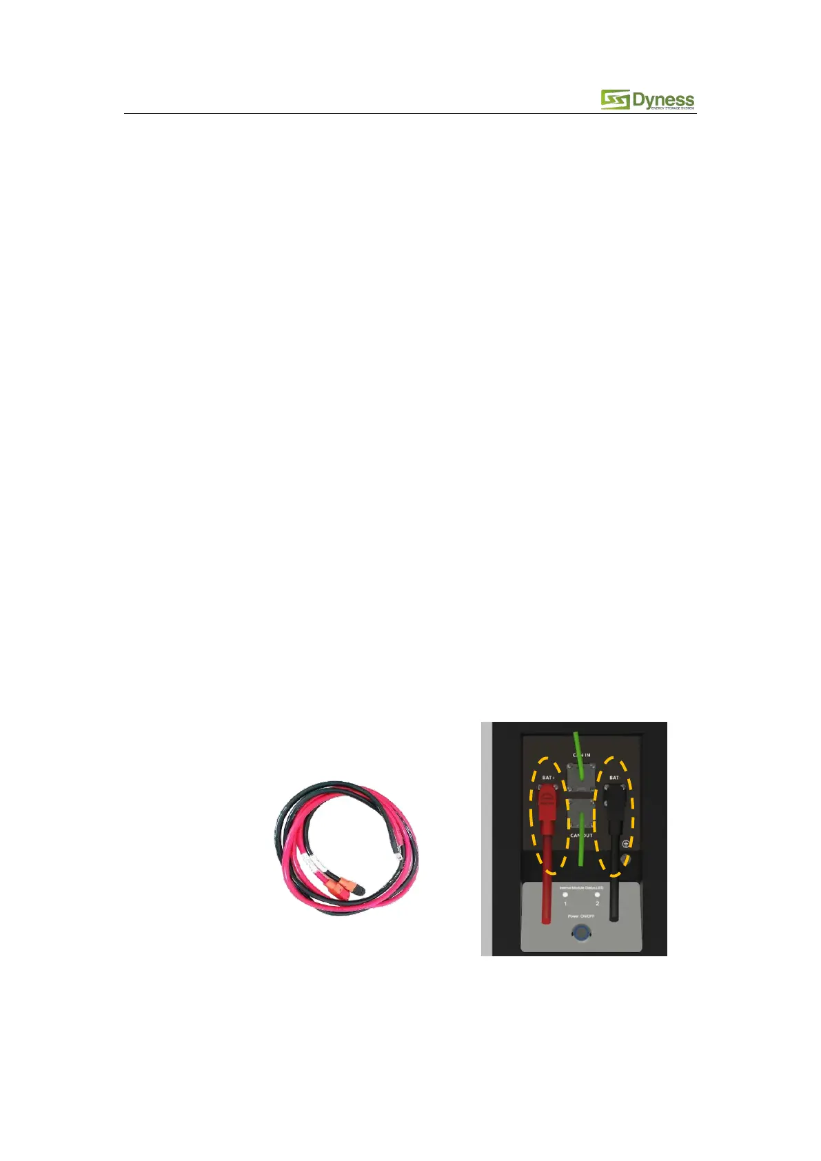
Keep the battery system at power off state, connect the power cable to the
interface on the input side of the inverter first, and then connect the power cable
to the interface on the battery side.
The battery output interface is a quick connector, and the power cable (positive,
negative) plug can be directly inserted into the battery socket. The power cable
cross section is 25 mm2.