Powerbox Pro series User Manual
27
Generally factory default DIP switch status of the master module in Powerbox Pro is setting 1.
When they are used in parallel, all the slave Powerbox Pro systems need to be opened the cover
and change the DIP switch of the master module to Slave Setting 1 (i.e. ADD: 0000),the master
powerbox Pro no need change.
Proceed as follows:
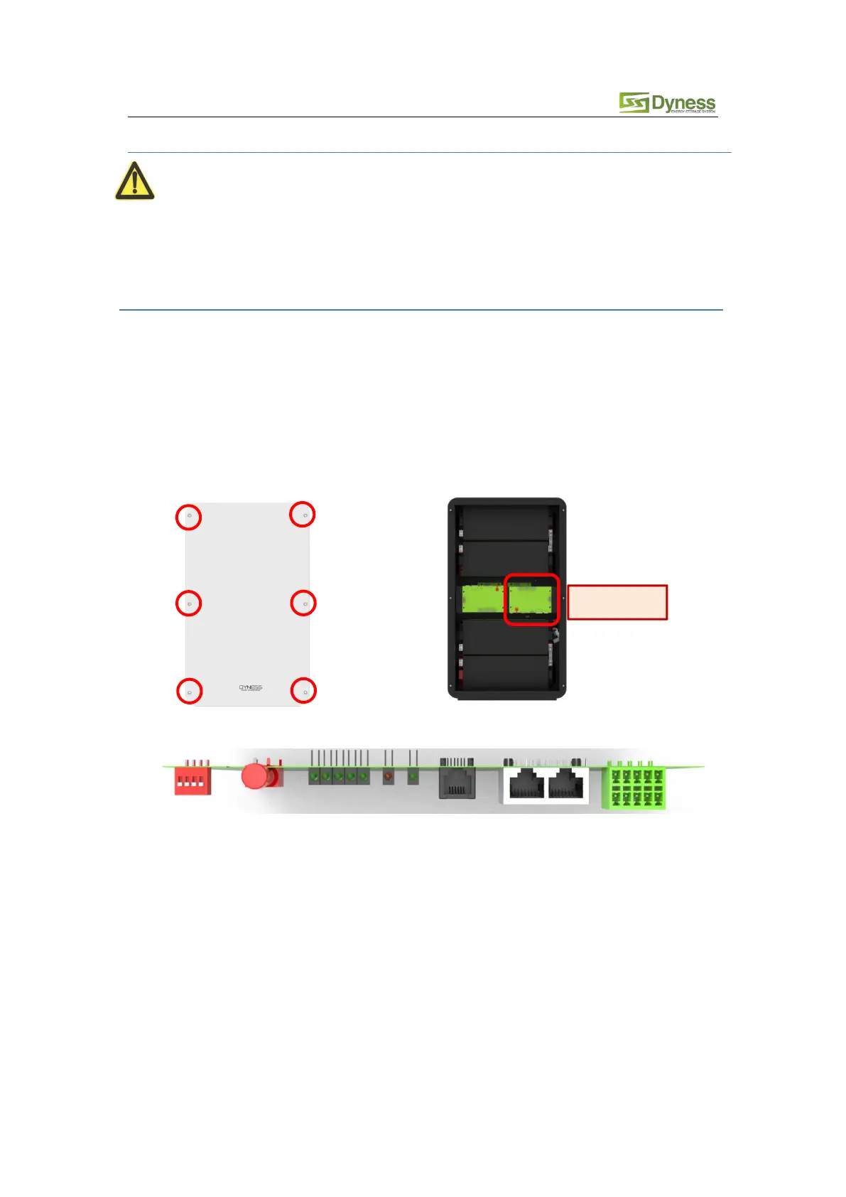
a. Remove the six screws on the Powerbox Pro and open the front panel.
b. Find the red DIP switch on the master battery PCB .
c. Change the DIP switch status to the original state (Mode5: i.e. ADD: 0000)
d. Re-install the front panel with six screws which were removed in step a.