63
@IST01530EEJ 019175A0 190411
CHOOSE THE SENSOR TO BE RECALIBRATED AND PROCEED AS DESCRIBED (CO SENSOR IS SHOWN
IN THIS EXAMPLE):
•
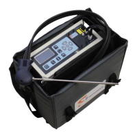
Connect the known concentration gas cylinder to the instrument as shown in the following scheme:
▲
Operator
Report header setup
Micromanometer
Language
►Calibration
CONFIGURATION
PASSWORD
0 0 0 0
PASSWORD
1 1 1 1
►CO
NO
NO
2
CALIBRATION
CO
►NO
NO
2
CALIBRATION
CO
NO
►NO
2
CALIBRATION
Action calibrate
►Applied 100.0
P
Measured 0
P
Is 2.22 uA
Ia 0.17 uA
Status original
CO CALIBRATION
Action calibrate
►Applied 100.0
P
Measured 0
P
Is 0.21 uA
Status original
NO CALIBRATION
Action calibrate
►Applied 100.0
P
Measured 0
P
Is 1.19 uA
Status original
NO
2
CALIBRATION
Enter the recalibration menu password
1111.
The installed sensors are shown, and can be chosen for
recalibration.
In the calibration screenshot, information about the
calibration in use and sensor output are displayed.
Action: selection of action to make
calibrate: save new calibration
set original: bring back original factory
calibration
set user: bring back last completed user
calibration
Applied: selection of cylinder gas concentration (ppm)
Measured: Actual sensor reading
Is: 'Is' current from the sensor
Ia: 'Ia' current from the sensor
Status: Shows calibration status:
original: factory original calibration in use
user: user calibration in use
saving: calibration saving in progress
user cal OK: user calibration successful
cal error: user calibration error
orig cal ok: restore of original cal successful
GAS CYLINDER COMBUSTION ANALYZER
P- P+ A
FLOW METER
0,5 l/m
1