INPUT ISOLATION TRANSFORMER INSTALLATION
Eaton 9155 UPS (8–15 kVA) User's Guide S 164201553 Rev G (www.eaton.com/powerquality)
19
Input
Output
L1
L2 (208V)
L2 (240V)
L1
L2
N
GND
Edge Grommet
Pilot Holes in Conduit Landing
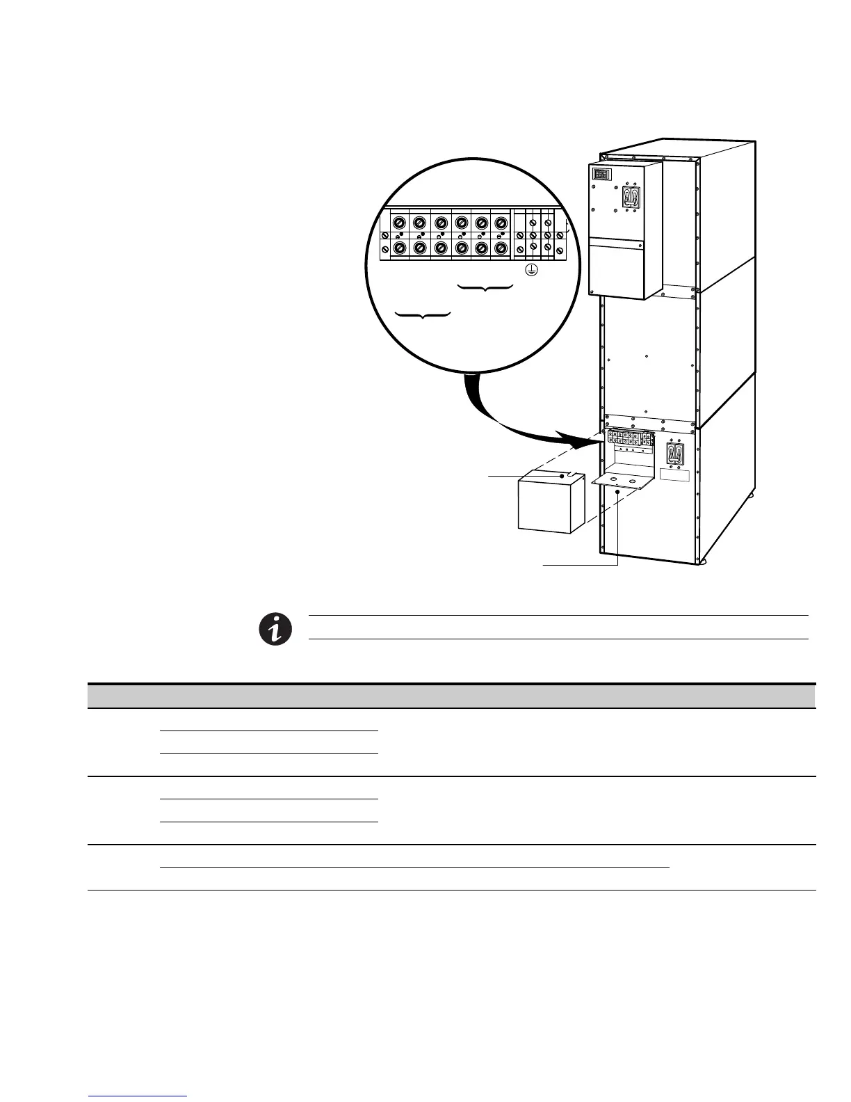
Figure 10. Input Isolation Transformer Hardwiring
NOTE Input neutral is supplied by the input isolation transformer.
Table 2. Input Isolation Transformer Terminal Block Wiring
Wire Function Terminal Position Input Circuit Breaker Rating Minimum Wire Size* Tightening Torque
Input
L1 TB1‐1
8 kVA
10 kVA
12 kVA
15 kVA
60A
80A
100A
100A
3 AWG (26.7 mm
2
)
2 AWG (33.6 mm
2
)
1 AWG (42.4 mm
2
)
1 AWG (42.4 mm
2
)
25 lb in
(2.83 Nm)
L2 (208V) TB1‐2
L2 (240V) TB1‐3
Output
L1 TB1‐4
8 kVA
10 kVA
12 kVA
15 kVA
4 AWG (21.2 mm
2
)
3 AWG (26.7 mm
2
)
2 AWG (33.6 mm
2
)
2 AWG (33.6 mm
2
)
25 lb in
(2.83 Nm)
L2 TB1‐5
Neutral TB1‐6
Ground
Output TB1‐7 8 AWG
25 lb in
(2.83 Nm)
Input TB1‐8 8 AWG
* Use only 75°C-rated copper wire. Minimum wire size is based on 120/208 full load ratings applied to NEC Code Table 310‐16. Code may require a larger
AWG size than shown in this table because of temperature, number of conductors in the conduit, or long service runs. Follow local requirements.