COMMUNICATION
Eaton 9155 UPS (8–15 kVA) User's Guide S 164201553 Rev G (www.eaton.com/powerquality)
54
LanSafe Power Management Software
Each Eaton 9155 UPS ships with LanSafe Power Management Software and an
interface cable. To begin installing LanSafe software, see the instructions
accompanying the Software Suite CD.
NOTE Use only the supplied communication cable to connect the UPS to your computer.
LanSafe software provides up-to-date graphics of UPS power and system data and
power flow. It also gives you a complete record of critical power events, and it
notifies you of important UPS or power information. If there is a power outage and
the Eaton 9155 UPS battery power becomes low, LanSafe software can automatically
shut down your computer system to protect your data before the UPS shutdown
occurs.
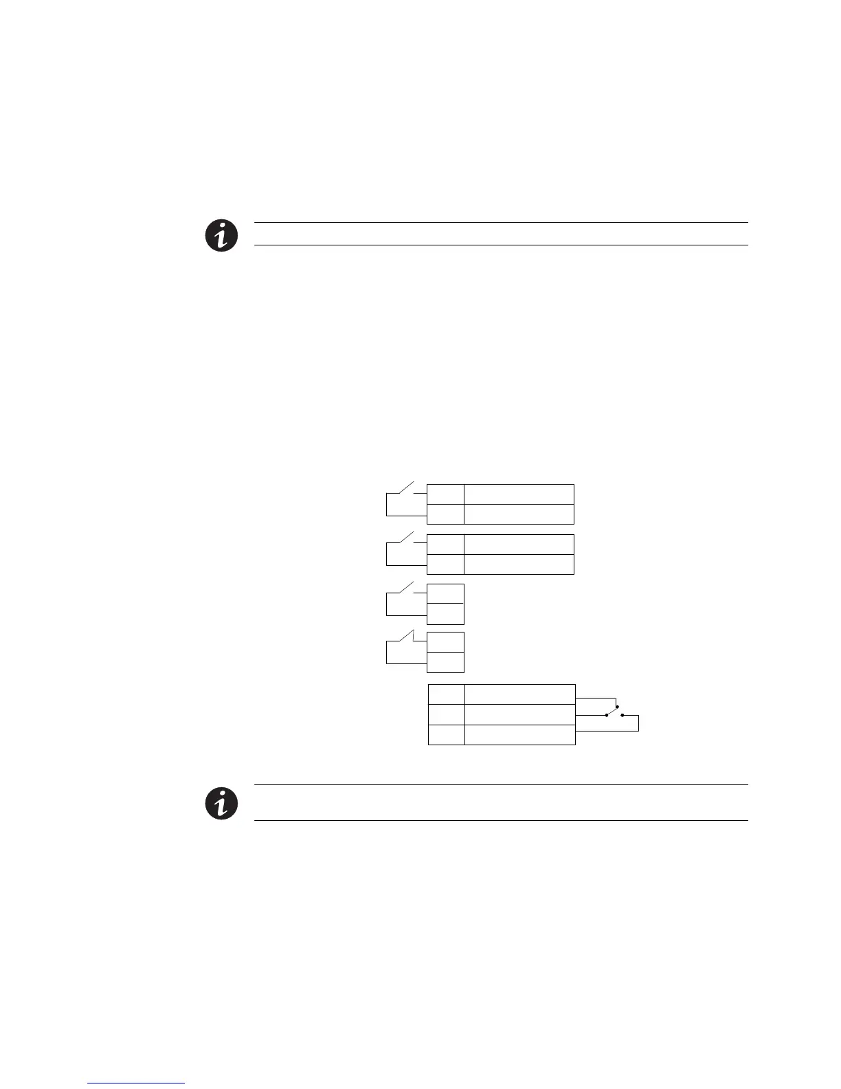
Control Terminals
The cables should be connected to the control terminals with a mating connector.
Input and output terminals have a functional isolation from terminal to terminal. They
are connected to the UPS chassis through individual 1 MΩ resistors.
+ Polarity
– Polarity
2
1
+ Polarity
– Polarity
2
1
2
1
2
1
Signal Input 1 (programmable)
Signal Input 2 (programmable)
REPO Normally Open
REPO Normally Closed
Normally Open
Normally Closed
1
2
Common
3
Relay Output
UPS
Connectors
(see Figure 36 on
page 49)
Figure 43. External Control Terminal Connections
NOTE If using a semiconductor switch type, pay attention to the proper polarity. A relay or other
mechanical control is preferred.