UPS-MOUNTED BYPASS SWITCH INSTALLATION
Eaton 9155 UPS (8–15 kVA) User's Guide S 164201553 Rev G (www.eaton.com/powerquality)
30
NOTE Input neutral must be wired for proper operation. Failure to connect an input neutral will void the
warranty. However, when wired with the optional isolation transformer, input neutral is supplied by the
isolation transformer.
Table 4. MBM/PDM Terminal Block (TB10) Wiring
Wire Function
Input Circuit
Breaker Rating
Minimum
Wire Size*
Tightening
Torque
Conduit Connection
(Entry Size)
Input
Ground 8 AWG
120 lb in
(13.5 Nm)
2” access hole for
1‐1/2” conduit
L1
8 kVA
10 kVA
12 kVA
15 kVA
60A
80A
100A
100A
4 AWG (21.2 mm
2
)
3 AWG (26.7 mm
2
)
2 AWG (33.6 mm
2
)
2 AWG (33.6 mm
2
)
Neutral
L2
Output
L1 3 AWG
120 lb in
(13.5 Nm)
2” access hole for
1‐1/2” conduit
Neutral 3 AWG
L2 3 AWG
Ground 8 AWG
* Use only 75°C-rated copper wire. Minimum wire size is based on 120/208 full load ratings applied to
NEC Code Table 310‐16. Code may require a larger AWG size than shown in this table because of
temperature, number of conductors in the conduit, or long service runs. Follow local requirements.
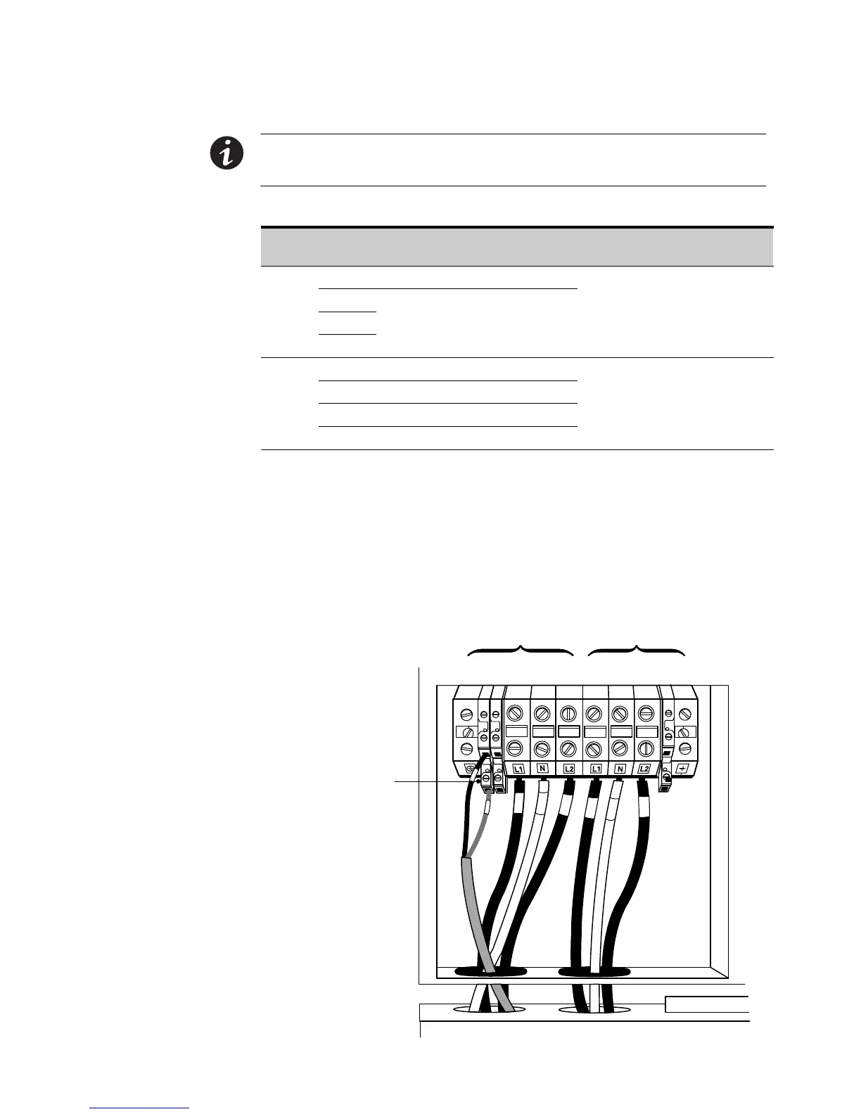
8. Connect the factory-installed wiring from the maintenance bypass switch to the
UPS terminal block (see Figure 20).
Connect the maintenance bypass (red and black) wires to TB1-2 (the A/B
maintenance bypass auxiliary contacts) on the UPS terminal block.
12 345678 9
A/B Maintenance
Bypass Auxiliary
Contacts
TB1
Input
Output
2A 8A
Figure 20. Wiring from Maintenance Bypass Switch to UPS