COMMUNICATION
Eaton 9155 UPS (8–15 kVA) User's Guide S 164201553 Rev G (www.eaton.com/powerquality)
51
Figure 39. Removing Knockout Tabs
4. Route the cable(s) to the approximate location of the cover access holes.
5. Connect the cables to the appropriate location.
See “Communication Options” on page 52 or “Control Terminals” on page 54
for detailed information.
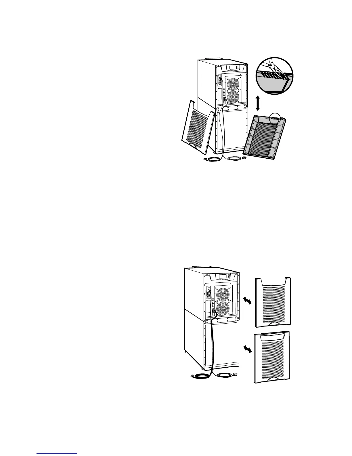
6. Reinstall the front covers, starting with the bottom cabinet (see Figure 40).
Hang the top edge of the cover on the cabinet first, then lower the bottom edge
and snap into place. Be sure the cables fit in the access holes in the covers.
7. Continue to “Operation” on page 57 to start up the UPS.
Figure 40. Reinstalling the Front Covers