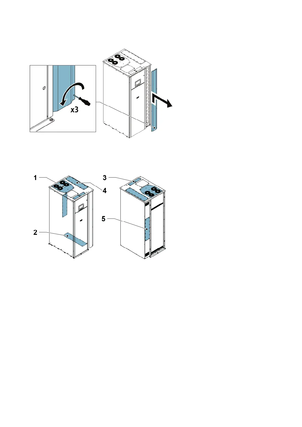
Figure 13. Removing the right panel
Figure 14. Gland plate locations
1. Top exhaust fan panel (optional)
2. Bottom cable access gland plate
3. Communication cable access gland
plates
4. Top cable access gland plate
5. Rear cable access gland plate
EATON 93PM G2 UPS USER’S AND INSTALLATION GUIDE P-164000956
-
February 2021 www.eaton.eu 4477

 Loading...