Page
vi
Figure
1-1
1-2
1-3
1-4
2-1
2-2
2-3
2-4
2-5
3-1
3-2
3-3
3-4
3-5
3-6
3-7
3-8
3-9
3-10
3-11
3-12
3-13
3-14
3-15
3-16
3-17
3-18
3-19
3-20
4-1
4-2
4-3
4-4
4-5
4-6
4-7
4-8
4-9
4-10
4-11
4-12
4-13
4-14
4-15
4-16
4-17
4-18
l.B.
694C694-02
FIGURES
Title Page
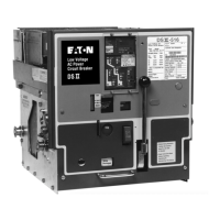
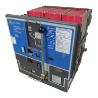
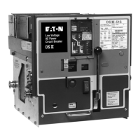
Type DSll Circuit Breaker Family .............................................................................................................. 1
Typical DSll Nameplate ............................................................................................................................ 3
Type DSLll Breaker with Integral Current Limiters .................................................................................... 4
DSll Breaker Shown on Compartment's Captive Extension Rails ............................................................ 4
DSll Breaker with Lifting Yoke Installed .................................................................................................... 6
DSll Breaker with One lnterphase Barrier Removed ................................................................................ 6
DSll Breaker with One Arc Chute Removed ............................................................................................ 7
DSll Levering Device Arm Shown in REMOVE Position .......................................................................... 7
Typical Fixed Type DSll Circuit Breaker .................................................................................................. 8
Type DSll Circuit Breaker (Front and Rear Views) .................................................................................. 9
Type DSLll Circuit Breaker (Front and Rear Views) .............................................................................. 10
Typical
OSI
I Faceplate ............................................................................................................................ 12
Type DSll-308 Pole Unit Assembly (Front View) .................................................................................... 13
Type DSll-308 Pole Unit Assembly (Rear View) .................................................................................... 13
Type DSll-516 Pole Unit Assembly (Front View) .................................................................................... 14
Type DSll-516 Pole Unit Assembly (Rear View) .................................................................................... 14
DSll lnterphase Barriers Being Removed .............................................................................................. 15
DSll Arc Chute Being Removed .............................................................................................................. 15
Typical Type DSll Tripping System Diagram .......................................................................................... 15
Type DSll Trip Actuator .......................................................................................................................... 16
Typical FronVRear View of Manual Spring Charge Mechanism ............................................................ 17
Typical FronVRear Views of Power Operated Spring Charge Mechanism ............................................ 18
Type DSll Circuit Breaker (Bottom View) ................................................................................................ 19
Anti-Pump Relay Shown Unmounted ...................................................................................................... 19
Power Operated DSll Breaker (Front Cover Removed) .......................................................................... 20
Latch Check Switch Operation ................................................................................................................
21
Undervoltage Trip Attachment Operation ................................................................................................
21
Overcurrent Trip Switch Operation .......................................................................................................... 22
Close Bar Guard Shown Installed .......................................................................................................... 22
Manual Charging of Breaker Closing Springs ........................................................................................ 23
Principal Parts
in
Manually Charged Spring Operated Mechanism ........................................................ 24
Manually Operated Spring-Charging Mechanism Details ...................................................................... 25
Principal Parts
in
Power Operated Mechanism (Close Spring Shown
in
Charged Position) .................. 26
Crank Shaft Assembly
Front View (Some Parts Omitted for Clarity) ...................................................... 27
Power Operated Spring-Charge Details .................................................................................................. 28
Four Basic Positions of Breaker and Linkage (Enlarged View of Trip Shaft) .......................................... 30
Emergency Spring-Charge on Power Operated Mechanism ..................................................................
31
Basic Schematic and Connection Diagrams for Power Operated Breaker ............................................ 32
Drawout Unit Position Indicator .............................................................................................................. 33
Shutter, Trip Plate and Trip Shaft Relationship ...................................................................................... 35
Shutter, Interlock Cam and Levering Device Arms Relationship ............................................................ 37
Close-Release Interlock to Discharge Springs on Levering Out ............................................................ 39
Close Interlock Preventing Efforts to Close Already Closed Breaker ..................................................... .40
Padlock Device (Locked Trip-Free with Shutter Raised) ........................................................................
41
DSLll-516 Circuit Breaker (Side View) .................................................................................................... 42
Blown Limiter lndicator ............................................................................................................................ 44
DSll-FT32 Fuse Truck (Front View) ....................................................................................................... .44
Effective
07
/97
Courtesy of NationalSwitchgear.com

 Loading...


