EDR-5000 IM02602007E
51X/67X INV Measured Ground Fault Protection
Elements
51X[1] ,51X[2]
All ground current elements are identically structured.
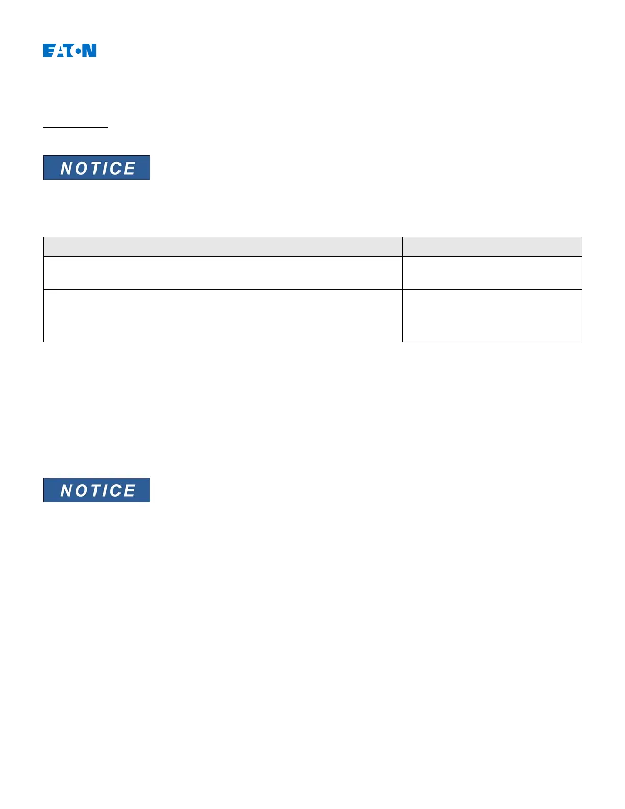
The following table shows the application options of the earth overcurrent protection element
Applications of the IG-Protection Module Setting in Option
ANSI 51X – Ground overcurrent protection,
non-directional
Device Planning menu
Setting: Non-directional
Measuring Mode:
Fundamental/TrueRMS
ANSI 67X – Ground overcurrent protection,
directional
Device Planning menu
Setting: Forward/Reverse
Measuring Mode:
Fundamental/TrueRMS
VX Selection: measured/calculated
Criterion
For all protection elements it can be determined, whether the measurement is done on basis of the »
Fundamental«
or if
»
TrueRMS«
measurement is used.
VX Selection
Within the parameter menu, this parameter determines, whether the earth current and the residual voltage is
»
measured«
or »
calculated«
.
Calculation is only possible, when phase to neutral voltage is applied to the
voltage inputs.
At setting »
measured«
the quantities to be measured, i. e. Residual voltage and
the measured ground current have to be applied to the corresponding 4
th
measuring input.
www.eaton.com 478

 Loading...


