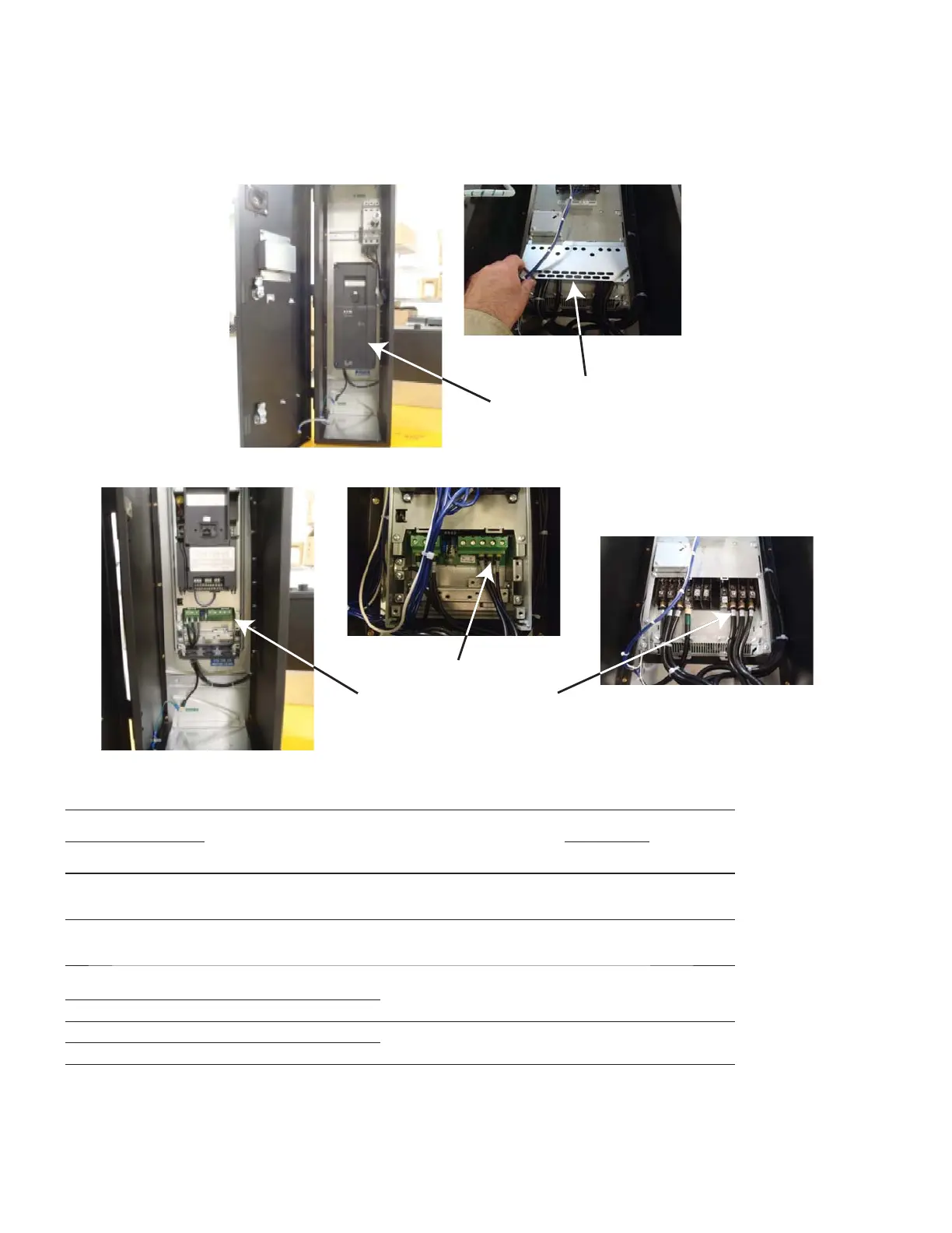
Remove Drive Cover and
Metal Terminal Covers to
Expose Output TB
Connections on Drive
Connect Motor Leads
Directly to the Drive Output
TB
For IntelliDisconnect models, wire directly to the drive output terminals or to the output contactor if the PE option is supplied.
Output Wiring Details
Horse Power Rating
Contactor’s
Current
Rating(Amps)
{AC-1}
Eaton
Contactor P/N
Instructions
See Eaton.com
Wire range
see note
Torque
Tool
208 V 230 V 460 V
lb.-in N-m
1, 2, 3 1, 2, 3 1,2,3,
5, 7.5,
22 XTCE007B pub51210
IL03407014Z
18-14 single/
double
11 1.2 0.8 x 5.5
1 x 6 mm (flat)
Size 2 pozidriv
5, 7.5,
10
5, 7.5,
10
10, 15,
20
40 XTCE018C pub51232
pub51211
IL03407014Z
14-8 single/
double
28 3.2 0.8 x 5.5
1 x 6 mm (flat)
Size 2 pozidriv
15, 20 15, 20 25,
30,40
60 XTCE040D pub51216
IL03407033Z
14-1 single
12-2 dual
29.2 3.3 0.8 x 5.5
1 x 6 mm (flat)
Size 2 pozidriv
- - 50 98 XTCE065D
25, 30 25, 30 60 110 XTCE080F pub51188
IL03407039Z
8-3/0 single
8- 2/0 double
124 14 5mm Hexagon
socket-head
- 40 75 160 XTCE115G
Note: For IntelliPass models two wires per terminal is not allowed because the factory installed
paralleling bridge uses one connection point
38
Wiring
H-Max Series Drives IntelliPass®/IntelliDisconnect® IL04008003E April 2013 www.eaton.com

 Loading...