Installation
M-Max Series Adjustable Frequency Drive MN04020003E—October 2013 www.eaton.com 41
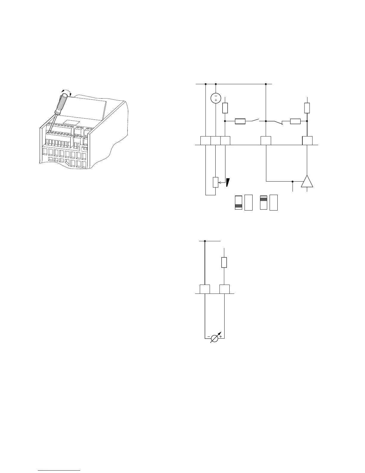
Analog Inputs
Connection area of the analog and digital inputs and outputs.
Control Signal Terminals (Digital and
Analog Inputs/Outputs)
The M-Max frequency inverter has two analog inputs for
specifying the frequency setpoint value and the actual value
return to the PI controller:
●
Control signal terminal 2 (AI1), voltage signal 0 (2)–10V,
input resistance 200k ohms
●
Control signal terminal 4 (AI2), current signal 0 (4)–20 mA,
Load resistance 200 ohms
Adjusting and the parameter definition of analog inputs are
described in “Analog Input (P2)” on Page 68.
The AI1 analog input (control signal terminal 2) is factory set
for the frequency setpoint (P6.2). The setpoint can be input
via an external potentiometer (recommended fixed
resistance: 1–10k ohms). The fixed resistance of the setpoint
potentiometer is fed from the frequency inverter via control
signal terminal 1 with +10V (maximum load rating: 10 mA).
Control signal terminals 3 and 5 are reference points (GND)
for the analog setpoint signals.
Analog Setpoint Inputs AI1 and AI2
Connection example: Potentiometer (4.7k ohms)
M22-R4K7; Article No. 229490
Analog Setpoint Value Signal, for Example, from a
Superordinate Controller (PLC)
12354
0 (4)–20 mA
AI1
GND
<10 mA
+10V Out
S3S2
GND
0–10V
200k ohms 200k ohms
200 ohms
200 ohms
AI2
PI-Ist
f-Soll
S2 = AI1V
(0–10V)
AI1
V mA
S3 = AI2 mA
(4–20 mA)
AI1
V mA
32
AI1
0–10V
200k ohms
GND
f-Soll
 Loading...


