5 Installation
5.3 Interfaces
30 MICRO PANEL XVS400 10.4"/12.1"/15" 10/2011 MN04802012Z-EN www.eaton.com
5.3.4 RS232 (System Port)
The RS232 interface is not electrically isolated. The GND pin is directly connected to the housing
potential.
Tab. 11 Pin assignment of the RS232 interface
Wiring Shielded cables must be used.
The maximum baud rate depends on the cable length:
Tab. 12 Relationship of cable length / baud rate
CAUTION
Non-isolated interfaces
The device may be damaged due to potential differences.
The GND terminals of all bus stations must be connected.
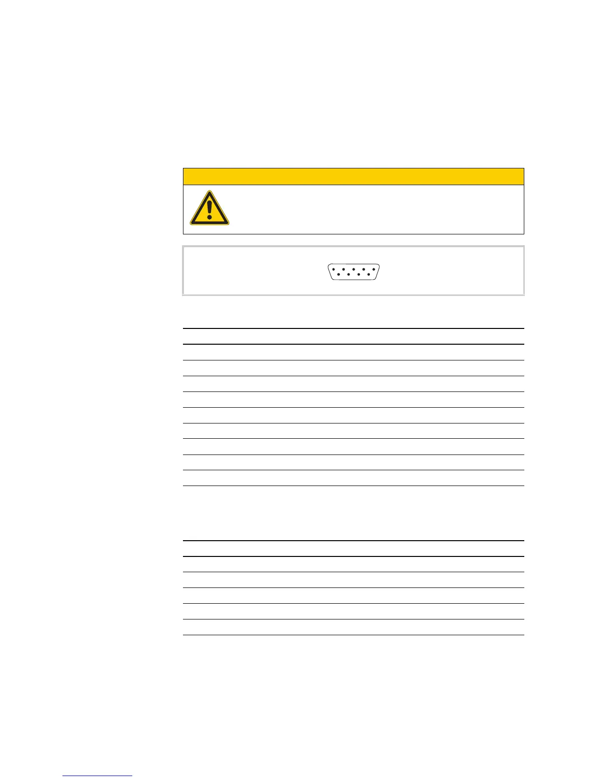
Fig. 13 RS232 interface (9-pin, D-Sub, male, UNC)
Pin Signal Assignment
1 DCD Data Carrier Detected
2 RxD Receive Data
3 TxD Transmit Data
4 DTR Data Terminal Ready
5 GND Ground
6 DSR Data Set Ready
7 RTS Request to Send
8 CTS Clear to Send
9 RI Ring Indicator