5 Installation
5.4 Mounting
MICRO PANEL XVS400 10.4"/12.1"/15" 10/2011 MN04802012Z-EN www.eaton.com 37
5.4.1 Mounting the device
1 Select the mounting position of the device as described in Chapter 5.2.2 Requirements for the
mounting position, 24.
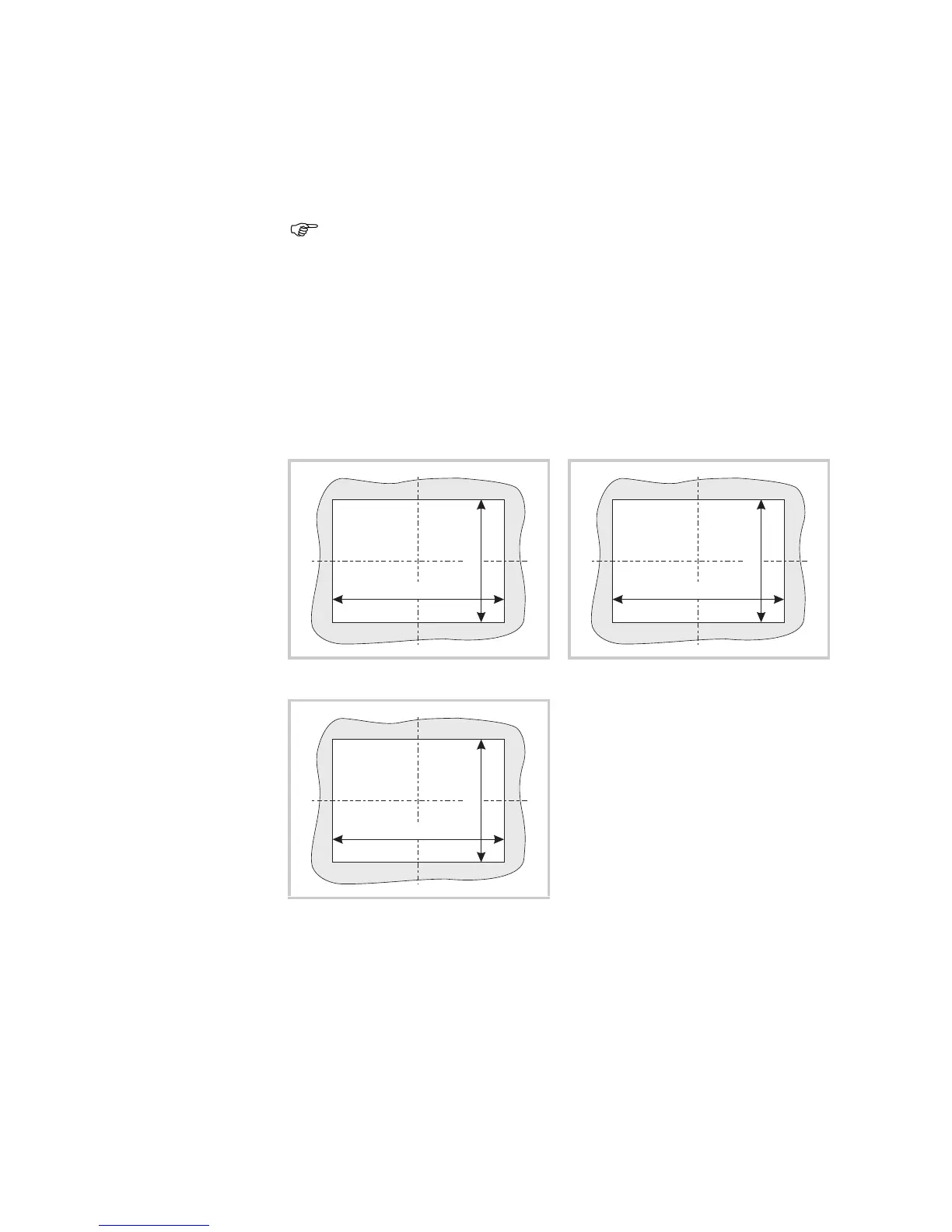
2 Prepare a mounting cutout for the device at the selected position:
Mounting cutout:
10.4" devices: 329 × 238 mm (±1 mm)
12.1" devices: 344 × 262 mm (±1 mm)
15" devices: 410 × 315 mm (±1 mm)
Material thickness at the mounting cutout 2…5 mm
An additional set of retaining brackets is required for mounting in accordance with
IP65 and for use in potentially explosive atmospheres. Please contact your supplier.
10.4" and 12.1" devices can be mounted horizontally or vertically, 15" devices must
only be mounted horizontally.
Fig. 19 Mounting cutout for 10.4" devices Fig. 20 Mounting cutout for 12.1" devices
Fig. 21 Mounting cutout for 15" devices