5 Installation
5.3 Interfaces
32 MICRO PANEL XVS400 10.4"/12.1"/15" 10/2011 MN04802012Z-EN www.eaton.com
5.3.5 Ethernet
For the approval in accordance with the standard UL 60950, consideration must be given to the condi-
tions for use in an end-product (according to Underwriters Labaratories Inc. (UL)):
In order to protect the device from potential internet threats, it should be connected to Ethernet
networks that are isolated from the internet or safety protected and isolated from the Corpo-
rate/Enterprise network by a firewall or router.
Tab. 13 Control LEDs of the Ethernet interface
Cable Use shielded twisted pair cable (STP) for networking:
For device to device connection: crossover cable
For connecting to the hub/switch: 1:1 patch cable
Maximum cable length: 100 m.
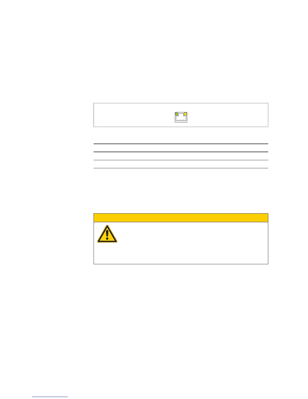
Fig. 14 Ethernet interface (RJ45 socket)
LED Signal Meaning
ACT (yellow) flashes Ethernet is active (data traffic)
LINK (green) lit Active network is connected and detected
CAUTION
Forces acting on the Ethernet interface
Communication can be disturbed and the connection mechanics damaged if the
Ethernet interface is exposed to severe vibration or the RJ45 plug connection is
pulled.
Protect the RJ45 connection from severe vibration.
Protect the RJ45 connection from pulling on the socket.