EN
11
EN
Relay 1
Relay 2
FAN
PTC (NTC)
4-20mA
MODBUS
RS485
0-10 V
IN1
IN2
IN3
IN4
Outputs that act as programmed in section 5. ADVANCED PARAMETERS
These outputs are potential free and with a maximum load of 5 amps at 230Vac.
In the operating mode with wall support, since we do not have the cooling of the motorfan itself, we will use the ventilation system that is equipped
with said support as standard to carry out this cooling. This output is 24Vdc and is activated whenever the inverter is activating the motor.
In this input we can connect a motor temperature probe, which will allow us to monitor its status. Allows the connection of a PTC or NTC probe.
The type of probe can be selected as programmed in section 5. ADVANCED PARAMETERS.
Connection of the pressure transducer or temperature sensor (always 4-20 mA), maintaining the correct polarity shown in the connections
diagram of the transducer itself.
In case of one sensor only, always connect to 4-20mA(1) input
In case of second sensor, connect it to 4-20mA(2) input
It allows the monitoring of the frequency inverter through the MODBUS communication protocol.
We can adjust the MODBUS communication configuration as programmed insection 6. FINE SETTINGS.
Note: For MODBUS parameter, refer to MODBUS section.
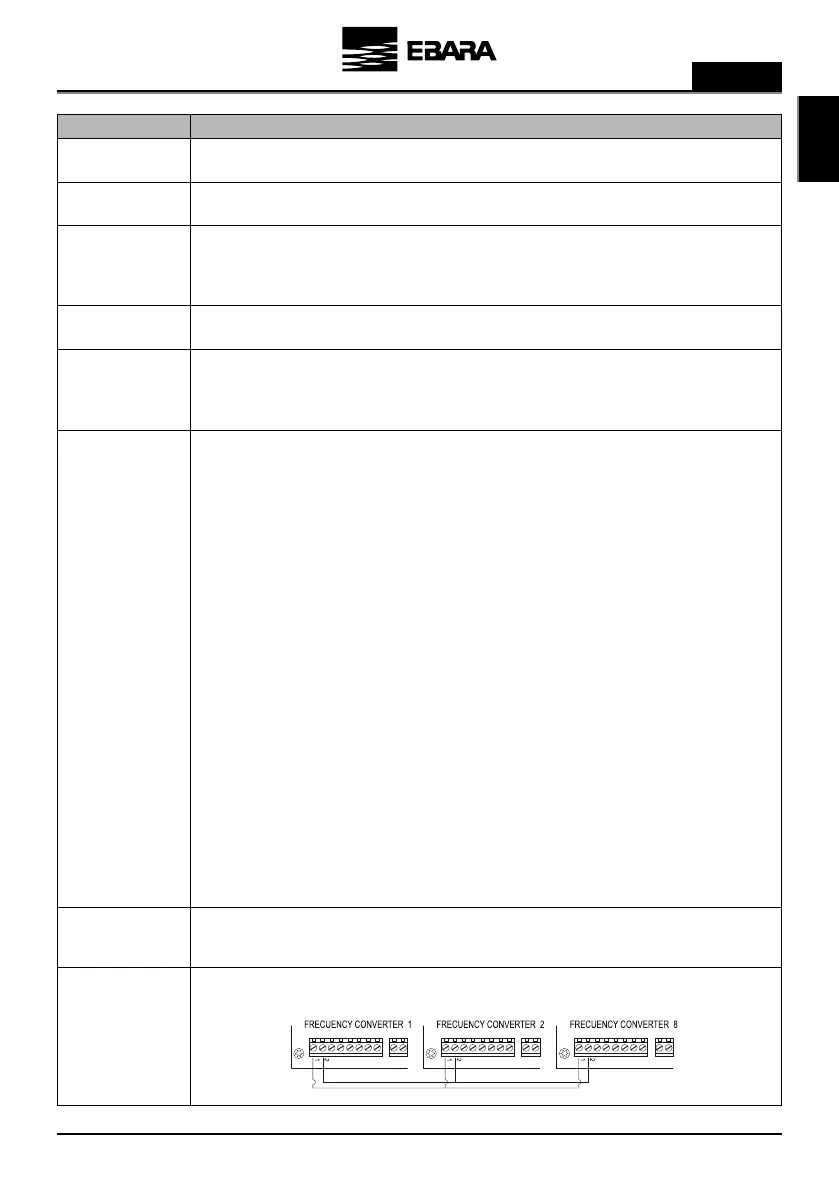
In these terminals, the interconnection of the different drives that we want tocommunicate must be carried out (maximum 8). The connection is
made point-to-point.Terminals 1 must be connected to each other in the same way as terminals 2.
External input that allows modifying the motor turning speed with the help of a potentiometer as specified in section 5. ADVANCED
PARAMETERS.
The input has 3 contacts: +10, AI1, GND.
If you have a potentiometer with its own power at 10V, connect the signal between between AI1 and GND.
If you have a potentiometer that does not have its own power supply, connect the potentiometer input between +10 and GND and the
potentiometer output to AI1.
This function can be enabled by closing one of the digtal input port and set it to “”Slave 0-10V” in 5. ADVANCED PARAMETERS.
The logic control is:
In modes A (Constant Pressure), B (Differential Pressure), D (Constant Temperature) and E (DifferentialTemperature): (Figure 3a on Page no. 383)
- Stop under 1V.
- Maximum speed above 9V.
- Linear acceleration/deceleration between 1V and 9V.
In mode C (Fixed Speed) logic depends on Slave 1V Setpoint and Slave 9 Setpoint value
a) Slave 1V setpoint is less than Slave 9V setpoint: (Figure 3b on
Page no. 383
)
- Stop under 0,5V
- Input signal under 1V and OFF --> Pump OFF
- Input signal under 1V and pump ON --> Slave 1V Setpoint
- Linear acceleration/deceleration between 1V and 9V.
- Input signal above 9V --> Slave 9V Setpoint
b) Slave 1V setpoint is greater than Slave 9V setpoint: (Figure 3c on
Page no. 383
)
- Stop above 9,5V
- Input signal above 9V and Pump OFF --> Pump OFF
- Input signal above 9V and pump ON --> Slave 9V Setpoint
- Linear acceleration/deceleration between 1V and 9V.
- Input signal under 1V --> Slave 1V Setpoint
In these inputs we can connect any potential-free contact that will perform the functions programmed in section 5. ADVANCED PARAMETERS.
NOTE: Do not supply these inputs with voltage!
SIGNAL DESCRIPTION