EBARA Pumps Americas Corporation
www.pumpsebara.com
9
rev. 01/19
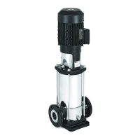
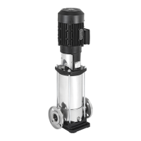
8.2.3 FASTENING DOWN
Bolt the pump on to a concrete base or suitable metal structure.
Use of anti-vibration supports is highly recommended in com-
mercial buildings (with occupants) if the concrete base is an in-
tegral part of the reinforced concrete structure of buildings.
When fastening, use a drill bit to center mark the 4 holes in the
base of the pump on the surface it is due to be installed on.
Use a drill to make 4 holes (dia. 12mm (15/32") for EVMSU 1, 3,
5, 10, 15, 20 pumps and dia. 14mm (9/16") for EVMU 32, 45, 64
pumps). Move the pump back into position, line it up with the
pipes and tighten the screws all the way.
The position of the fastening holes is also illustrated in section 15.6.
8.2.4 PIPEWORK
In addition to the instructions given below, also comply with the
general instructions found in sect. 15.7 of the manual and with
the directions in fig. 1.
Suction and discharge piping must be sized to
withstand the maximum working pressure of the
pump.
WARNING!
It is recommended that a pressure gauge be installed on the
discharge line before the check valve and isolating valve. Use
adequate supports for the suction and discharge lines to avoid
stress on the pump flange. If the pump is installed with a suc-
tion lift arrangement (liquid level lower than the pump) and it
feeds an open circuit, install a foot valve at the end of the suc-
tion line and use a hose connected to the pump.
Ensure that available NPSH is greater than NPSH
required by the pump. Insufficient NPSH will
result in cavitation, which reduces pump
performance and may result in damage to the
pump. Refer to the pump curves.
8.2.5 ELECTRICAL CONNECTION
Electrical connections must be made by qualified
personnel. Motor and circuit protection must be
appropriately sized. Observe all applicable codes
and standards.
Connect the electrical supply to the pump, following the motor
manufacturer’s instructions.
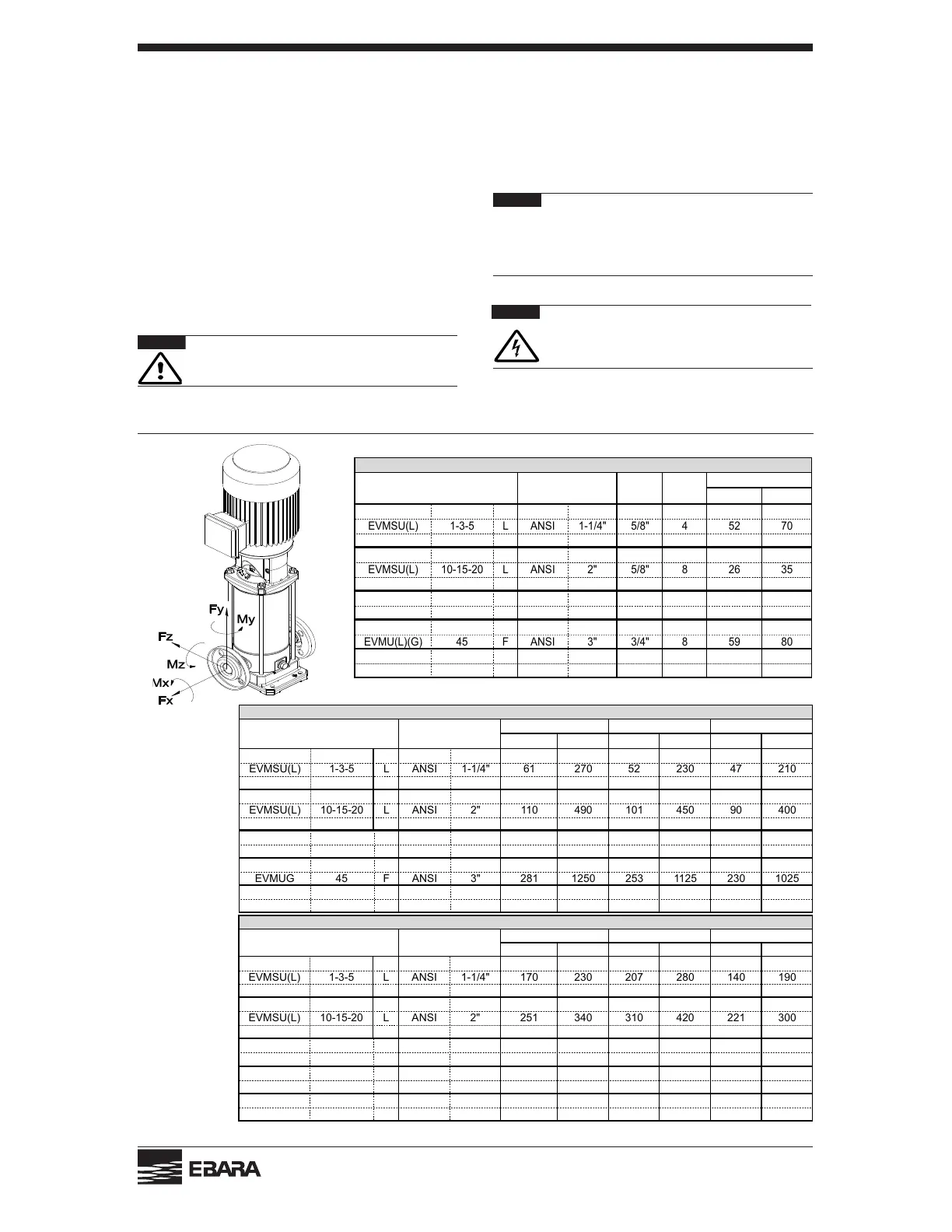
8.3 FLANGE LOADING AND TIGHTENING TORQUES
WARNING!
[lb-ft] [Nm]
EVMSU(L) 1-3-5 F ANSI 1-1/4" 5/8" 4 52 70
EVMSU(L) 1-3-5 L ANSI 1-1/4" 5/8" 4 52 70
EVMSU(L) 1-3-5 N - 1-1/4" M10 2 22 30
EVMSU(L) 10-15-20 F ANSI 2" 5/8" 8 26 35
EVMSU(L) 10-15-20 L ANSI 2" 5/8" 8 26 35
EVMSU(L) 10-15-20 N - 2" M12 2 37 50
EVMU(L)(G)
32
F ANSI 2-1/2" 5/8"
45980
EVMU(L)(G) 32 F ANSI 2-1/2" 3/4" 8 59 80
EVMU(L)(G) 45 F ANSI 3" 5/8" 4 59 80
EVMU(L)(G) 45 F ANSI 3" 3/4" 8 59 80
EVMU(L)(G) 64 F ANSI 4" 5/8" 8 59 80
EVMU(L)(G) 64 F ANSI 4" 3/4" 8 74 100
FLANGE TIGHTENING TORQUE
No. of
Bolts
Models Flange Bolt Size
Tightening torque
[lb] [N] [lb] [N] [lb] [N]
EVMSU(L) 1-3-5 F ANSI 1-1/4" 61 270 52 230 47 210
EVMSU(L) 1-3-5 L ANSI 1-1/4" 61 270 52 230 47 210
EVMSU(L) 1-3-5 N - 1-1/4" 61 270 52 230 47 210
EVMSU(L) 10-15-20 F ANSI 2" 110 490 101 450 90 400
EVMSU(L) 10-15-20 L ANSI 2" 110 490 101 450 90 400
EVMSU(L) 10-15-20 N - 2" 110 490 101 450 90 400
EVMU(L)
32
F ANSI 2-1/2" 472 2100 416 1850 382 1700
EVMUG 32 F ANSI 2-1/2" 236 1050 208 925 191 850
EVMU(L) 45 F ANSI 3" 562 2500 506 2250 461 2050
EVMUG 45 F ANSI 3" 281 1250 253 1125 230 1025
EVMU(L) 64 F ANSI 4" 753 3350 674 3000 607 2700
EVMUG 64 F ANSI 4" 377 1675 337 1500 303 1350
Strain Y [lb] Strain Z [lb]
ALLOWABLE STRAIN ON THE FLANGE
Models
Strain X
Flange
WARNING!
[lb-ft] [Nm] [lb-ft] [Nm] [lb-ft] [Nm]
EVMSU(L) 1-3-5 F ANSI 1-1/4" 170 230 207 280 140 190
EVMSU(L) 1-3-5 L ANSI 1-1/4" 170 230 207 280 140 190
EVMSU(L) 1-3-5 N - 1-1/4" 170 230 207 280 140 190
EVMSU(L) 10-15-20 F ANSI 2" 251 340 310 420 221 300
EVMSU(L) 10-15-20 L ANSI 2" 251 340 310 420 221 300
EVMSU(L) 10-15-20 N - 2" 251 340 310 420 221 300
EVMU(L)
32
F ANSI 2-1/2" 885 1200 1106 1500 811 1100
EVMUG 32 F ANSI 2-1/2" 442 600 553 750 406 550
EVMU(L) 45 F ANSI 3" 959 1300 1180 1600 848 1150
EVMUG 45 F ANSI 3" 479 650 590 800 424 575
EVMU(L) 64 F ANSI 4" 1069 1450 1291 1750 922 1250
EVMUG 64 F ANSI 4" 535 725 645 875 461 625
ALLOWABLE TORQUE ON THE FLANGE
Models Flange
Torque X Torque Y Torque Z