March 2013 61 IPV58
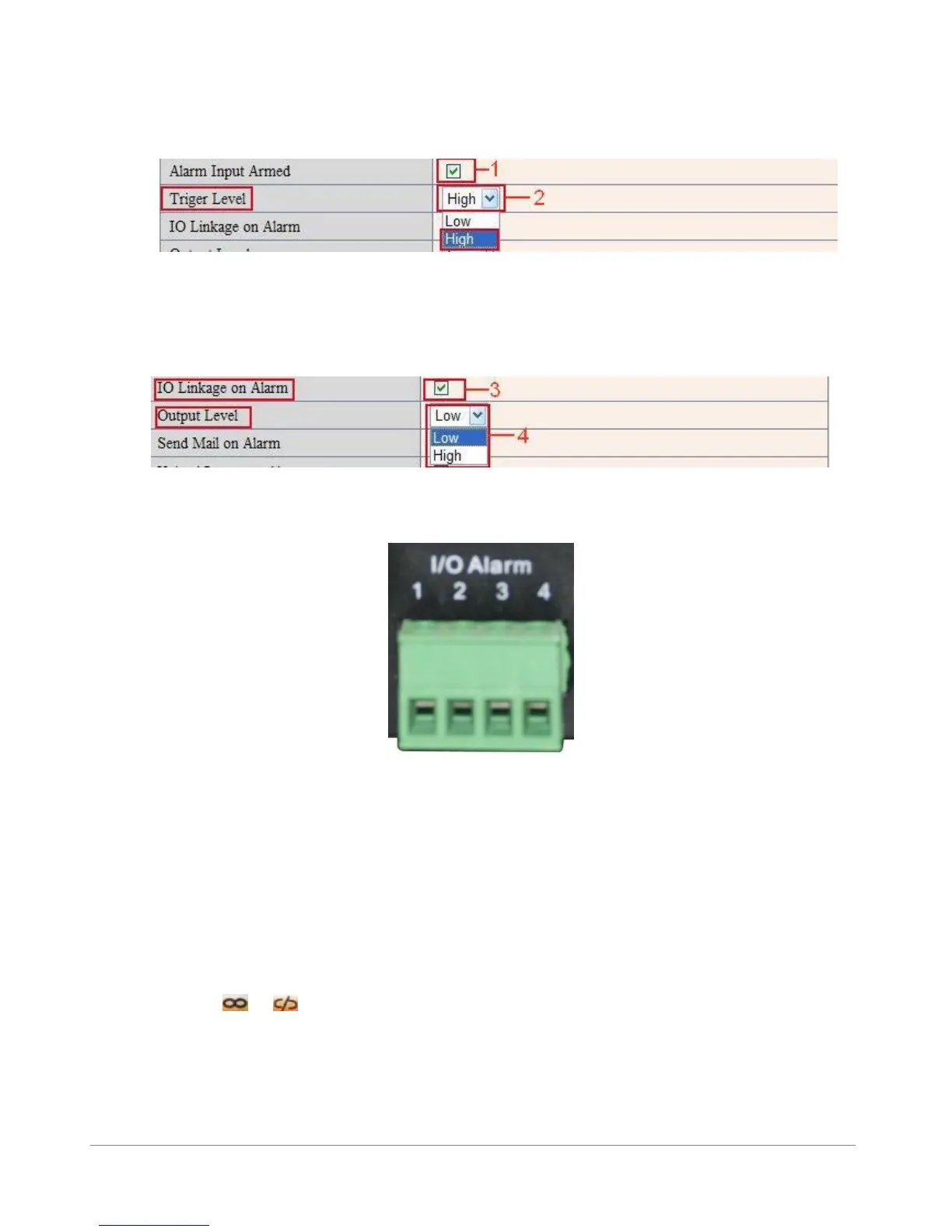
There are two options for Trigger Level. (Figure 10.0)
High: When the external alarm device is close, then the alarm triggered.
Low: When the external alarm device is switching off, then the alarm triggered.
Figure 10.1
There are two options for Output Level. (Figure 10.1)
High: When chosen, the IO Pins work as a switch that is closed.
Low: When chosen, the IO Pins work as a switch that is switching off.
Figure 10.2
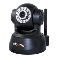
3.12.4 IO Pins for IO Alarm Linkage
Figure 10.3
I/O PINS: 1 Output 2 Output 3 Alarm input 4 Input (GND)
Input pins: The input pins can be used for 1-way external sensor input. For example, you may connect a
Passive Infrared Sensor (PIP) to it for motion detection. When external sensor triggered, IP CAMERA can be
programmed to send an e-mail with picture or control the internal relay output.
If you link an external alarm device to Pins 3 and 4, when Alarm Input Armed is selected (Figure 10.0),
external alarm is enabled.
Output pins: The output pins can be enable IO linkage on alarm.
You can also use & to control IO output Switch ON/OFF (See Figure 4.4).
NOTE: All the pins work as switch only.
Another cool feature for use of the I/O in/output is to connect a X10 SM10 or PH7208 interface. This way
you are able to turn on a light or sound an alarm when motion is detected.