pag.21
LB 381 BLU 500 -1400 PR / MD B
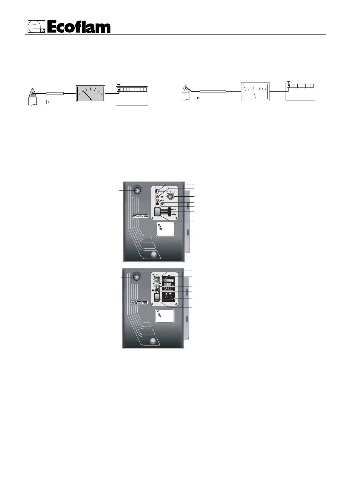
IONIZATION CURRENT
1
min. 1,5 µA
50
A
SATRONIC DMG 972
DESCRIPTION OF THE CONTROL PANEL OF THE BURNER
1 - fuse
2 - termal lock-out lamp
3 - cover
4 - working lamp
5 - cover
6 - main switch I / O
7 - reset key
8 - selector
0
I
1
2
6
3
5
4
7
0
AUTO
8
A
B
F
C
E
D
G
0
AUTO
0
I
K6
RWF 40
PGM
EXIT
A - selector :
0 =
operating elements locked in an
intermediate position
1 =
operation on maximum capacity
2 =
operation on minimum capacity
3 =
automatic operation
B - working lamp
C - termal lock-out lamp
D - fuse
E - Modulating unit RWF 40
F - main switch I / O
G - reset key
LANDIS & STAEFA
1
LGB21-LGB22 min. 3 µA
LMG21-LMG22 min. 2 µA
With the burner switched off, connect a DC microammeter with a 0÷50 or 0÷100 µA dial. When the burner
is running, and is properly adjusted, the value read must be steady and never be smaller than 3 µA (1,5 µA
Satronic).





 To Next Page