E
ecaldwellSep 23, 2025
Why EDAN M3 has no SpO waveform 2?
- CCody RobinsonSep 23, 2025
If there is no SpO waveform 2 on the EDAN Monitor, the sensor or SpO module may be damaged. Replace the sensor and confirm the failure.
Why EDAN M3 has no SpO waveform 2?
If there is no SpO waveform 2 on the EDAN Monitor, the sensor or SpO module may be damaged. Replace the sensor and confirm the failure.
What to do if my EDAN M3 device is occasionally stoned?
If your EDAN Monitor device occasionally freezes, this could be due to: * Moment intensive interference of network: Check the power supply and grounding system. * Poor performance of the power board: Replace the power board. * Poor performance of the Main control board: Replace the Main control board.
What to do if EDAN M3 Monitor recorder can not execute printing operation?
If the EDAN Monitor recorder is not printing, it might be due to: 1. Recorder has no paper or paper bail is not pressed down: Install paper and press down the paper bail. 2. Recorder failure: Replace the recorder. 3. Driving power of the recorder has failure: Replace the power supply. 4. Connecting wire of the recorder is damaged: Replace or repair the connecting wire of the recorder.
What to do if EDAN Monitor shows no display after power-on, power indicator light is not on or fan does not run?
If the EDAN Monitor shows no display after being powered on, and the power indicator light is off or the fan isn't running, it could be due to: * Fuse damage (If has fuse on): Replace the fuse. * Power damage: Replace the power board. * Component short-circuit: Anchor the short-circuit component.
What to do if EDAN M3 keys are disabled?
If the keys on your EDAN Monitor are disabled, it could be because: * The keyboard is damaged: Replace the keyboard. * The connecting wire of the keyboard is damaged: Replace or repair the connecting wire of the keyboard.
What to do if EDAN Monitor power indicator does not light on, however, the fan runs normally and the indicator of keyset lights on?
If the power indicator is off, but the fan is running and the keyset indicator is on for the EDAN Monitor, the +5V DC power supply may have failed. Replace the power.
Why EDAN Monitor SpO waveform has 2 strong interference?
If the SpO waveform on your EDAN Monitor has strong interference, it could be because: * The patient is moving: Keep the patient quiet. * The environment light is very intensive: Weaken the light intensity in the environment.
Why EDAN Monitor SpO value is 2 inaccurate?
If the SpO value is inaccurate on the EDAN Monitor, a coloring agent may have been injected into the patient's body. Remove the coloring agent before performing the measurement.
What to do if EDAN M3 can not be linked into network?
If your EDAN Monitor can not be linked into a network, it might be due to: * Network linking wire is damaged: Check and repair network linking wire or HUB. * Network bed No. conflicts: Change bed No. * Main control board failure: Replace Main control board.
What to do if EDAN M3 shows no display or screen goes black during normal operation?
If the EDAN Monitor shows no display or the screen goes black during normal operation, even though the power supply seems normal, it could be due to: * Power switch board damage: Replace the Power switch board. * Bad connecting wire of display: Repair or replace connecting wire. * Damage of Main control board: Replace Main control board. * Keyboard display driver failure: Replace keyboard main control board.
Describes EDAN's rights and permitted use of the publication, emphasizing confidentiality and authorized access.
Outlines EDAN's responsibility for safety, reliability, and performance under specific conditions.
Highlights that the monitor is not for family use and not for treatment purposes.
Explains the meaning of WARNING, CAUTION, and NOTE labels used in the manual.
Details the version history and release date of the service manual.
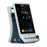
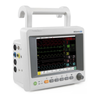
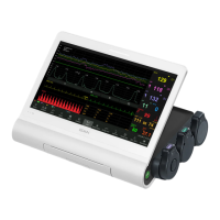
Provides a general description of the M3 Vital Signs Monitor, its capabilities, and intended use.
Describes the division of the LCD screen into parameter, waveform/trend, and information areas.
Details the various icons displayed on the monitor interface and their corresponding meanings.
Explains the indicators for alarm status and battery charging on the monitor.
Details the functions of the ON/OFF and SILENCE buttons for monitor control and alarm management.
Explains the operation of NIBP START/STOP, TREND/WAVEFORM, and RECORD buttons.
Describes the MENU, UP, OK, and DOWN buttons for navigating and selecting options.
Describes the recorder's paper inlet cover located on the left side of the monitor.
Details the SpO2 and NIBP sensor connectors on the front panel.
Explains the equipotential grounding, power supply socket, and network interface on the rear panel.
Identifies the battery compartment and fuse box located on the bottom panel.
Explains the different icons indicating battery status (charging, full, empty) on the monitor screen.
Describes the color of the charger indicator light to show battery charging status.
Provides guidelines for replacing the battery and important safety warnings related to battery handling.
Lists the five main parts of the monitor: parameter measuring, main control, interface, power supply, and auxiliary parts.
Details the functions of the parameter measuring and interface parts of the monitor.
Explains the main control board and the power supply part of the monitor system.
Mentions the RJ45 port for on-line system software upgrades.
Illustrates the hardware structure and interconnections between monitor components.
Describes the role of the power module in providing DC supplies to other boards.
Details the main control board's schematic diagram and its system control functions.
Explains the CPU's function as the kernel of the main control board for data processing and control.
Describes the functions of the RTC, Ethernet Controller, and LCD Controller.
Explains the keyboard module's role as a man-machine interface and its schematic diagram.
Details the recorder module's design for driving the line thermal recorder and its operational principles.
Presents a general diagram illustrating the flow and functions of the system software.
Details the various tasks performed by the system software and their execution cycles.
Illustrates the overall system structure and how parameters are acquired and processed.
Explains the NIBP measurement method, operating modes, and patient types.
Describes the principles behind SpO2 measurement, including light absorption and signal processing.
Guides on how to unpack the monitor and perform initial checks for damage and completeness.
Provides instructions for connecting the AC power line to the monitor.
Details the steps for powering on the monitor and what to expect on the screen.
Instructions for connecting patient sensors and verifying recorder paper installation.
Covers safety regulations for use with other equipment and explosion hazard warnings.
Outlines the steps for checking the monitor's appearance, function, and performing routine safety checks.
Recommends NIBP calibration for accuracy and outlines the procedure.
Provides an exploded diagram showing the main components and fasteners of the monitor.
Lists and identifies the parts included in the front shuck assembly of the monitor.
Lists and identifies the parts included in the rear shuck assembly of the monitor.
Lists and identifies the parts associated with the bracket assembly.
Provides solutions for common device failures like no display after power-on or black screen operation.
Offers solutions for intermittent waveform display and disabled operations or measurement functions.
Addresses display failures, disabled keys, and sound issues with the monitor.
Provides solutions for recorder operation problems and network connectivity issues.
Covers issues related to the power board, fuse blowing, and parameter measurement errors.
Addresses problems with SpO2 waveform interference and inaccurate SpO2 values.
Provides instructions for cleaning the monitor's exterior and display screen, including agent recommendations.
Details the maintenance, cleaning, and sterilization procedures for reusable and disposable blood pressure cuffs.
Outlines the recommended methods for cleaning and maintaining the SpO2 sensor.
Explains how to enter and navigate the maintenance menu for system settings.
Describes available user settings such as network type, bed number, language, and alarm sound.
Details the factory maintenance functions, including setting SpO2/NIBP modules and power type.
Lists recommended SpO2 sensors and extension cables compatible with the monitor.
Details the available cuff sizes and other necessary NIBP accessories.
Explains the warranty period, repair, adjustment, or replacement policy.
Lists conditions and misuse that may void the product warranty.
Outlines the procedure for submitting a service claim and receiving a solution.
Details the steps for handling warranty claims, including RMA and part returns.
Provides guidelines for packaging and shipping defective parts back to EDAN.
Defines the product's classification regarding electroshock protection, EMC, and ingress protection.
Lists the physical dimensions, weight, and environmental operating conditions for the monitor.
Details the specifications for the monitor's display, battery, and built-in recorder.
Describes data review capabilities and detailed NIBP measurement specifications.
Provides detailed specifications for NIBP measurement across different patient modes and accuracy.
Details the measurement ranges, resolution, and accuracy for SpO2 and Pulse Rate.
Covers SpO2 anti-interference features and specifications for the optional Nellcor module.
| Resolution | 320 x 240 pixels |
|---|---|
| Weight | 1.2 kg (with battery) |
| Display Type | TFT LCD |
| ECG | 3/5-lead ECG |
| Optional Parameters | EtCO2 |
| Battery | Rechargeable lithium-ion |
| Networking | Wired network |
| Atmospheric Pressure | 700 hPa to 1060 hPa |