3-7
Connecting to the Console Port
3
Connecting to the Console Port
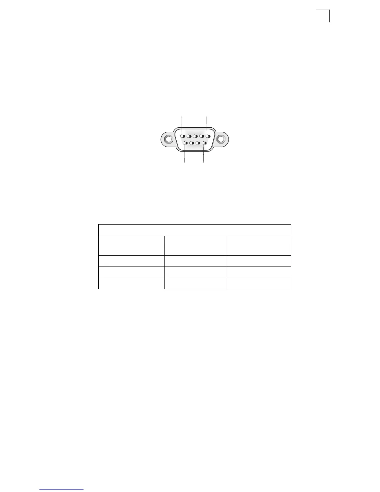
The DB-9 serial port on the switch’s front panel is used to connect to the switch for
out-of-band console configuration. The on-board configuration program can be
accessed from a terminal or a PC running a terminal emulation program. The pin
assignments used to connect to the serial port are described in the following figure
and table.
Figure 3-7. Serial Port (DB-9 DTE) Pin-Out
Wiring Map for Serial Cable
The serial port’s configuration requirements are as follows:
• Default Baud rate—9,600 bps
• Character Size—8 Characters
• Parity—None
• Stop bit—One
• Data bits—8
Table 3-1. Serial Cable Wiring
Switch’s 9-Pin
Serial Port
Null Modem PC’s 9-Pin
DTE Port
2 RXD (receive data) <---------------------------- 3 TXD (transmit data)
3 TXD (transmit data) -----------------------------> 2 RXD (receive data)
5 SGND (signal ground) ------------------------------ 5 SGND (signal ground)
No other pins are used.
1
5
6 9