20 CMDN Manual
PIN 1
PIN 14
PIN 13
PIN 25
DB25 MALE
(REAR VIEW)
CMDN(C)/SMDN(C)LSS4
1 2 34567 8 910
23 7
TO PT1-S SERIAL PRINTER
(REAR VIEW)
[CMDN-015.CDR]
TB1
RS-485
+24V
COM
+
+
+
+
TO LSS4 OR LSSPS
24 VDC SUPPLY
TO ADDITIONAL
ANNUNCIATORS
1
1
1
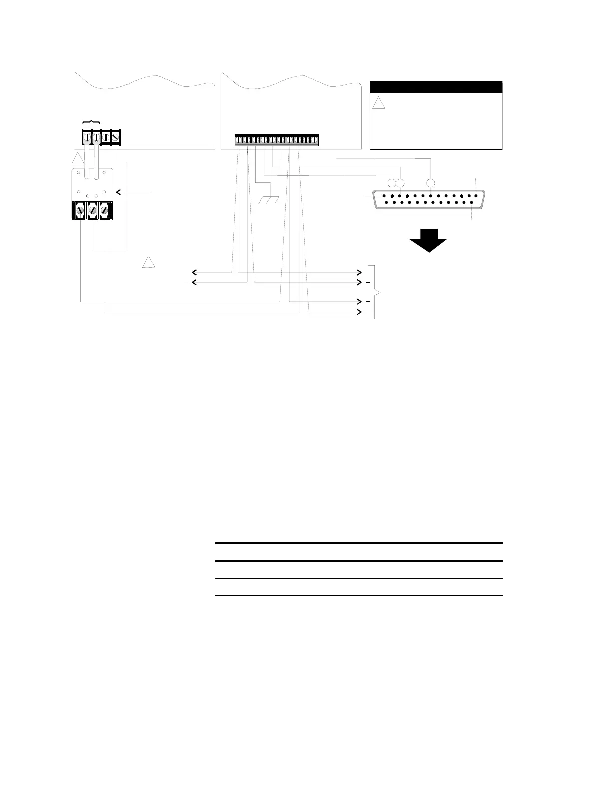
NOTES
SUPERVISED AND POWER LIMITED.
2. ROUTE POWER LIMITED WIRING
SEPARATE AND AWAY FROM NON-
POWER LIMITED WIRING.
3. ALL WIRING 18 AWG, TWISTED.
REMOTE RS-485
INTERFACE
P/N 130285
(Used only on motherboard
versions prior to 1.5)
LSS4 To CMDN(-C)/SMDN(-C) Wiring
The Remote RS-485 Isolator (P/N 130285) provides electrical
protection for the RS-485 wiring leaving the panel. LSS4 motherboard
versions 1.5 or higher now include the RS485 interface.
Annunciator Setup - IRC-3 and FCC/PCPU
RS-485 Data Line Configuration
Jumper Setup
Jumpers JP1 and JP2 on the annunciator are RS-485 terminating
jumpers. The RS-485 terminating jumpers should be installed ONLY at
the first and last physical connection locations on the data line.
Jumper Setup
Function P3 P4
Class B (channel 0) IN *
Class A (channel 1) OUT IN
* in or out = no effect
Switch Setup
All Dip switches should be set in the OFF position. SW1-4 clears the
database and loads the default parameters. To default the panel, turn
SW1-4 on, power down, then restore power.