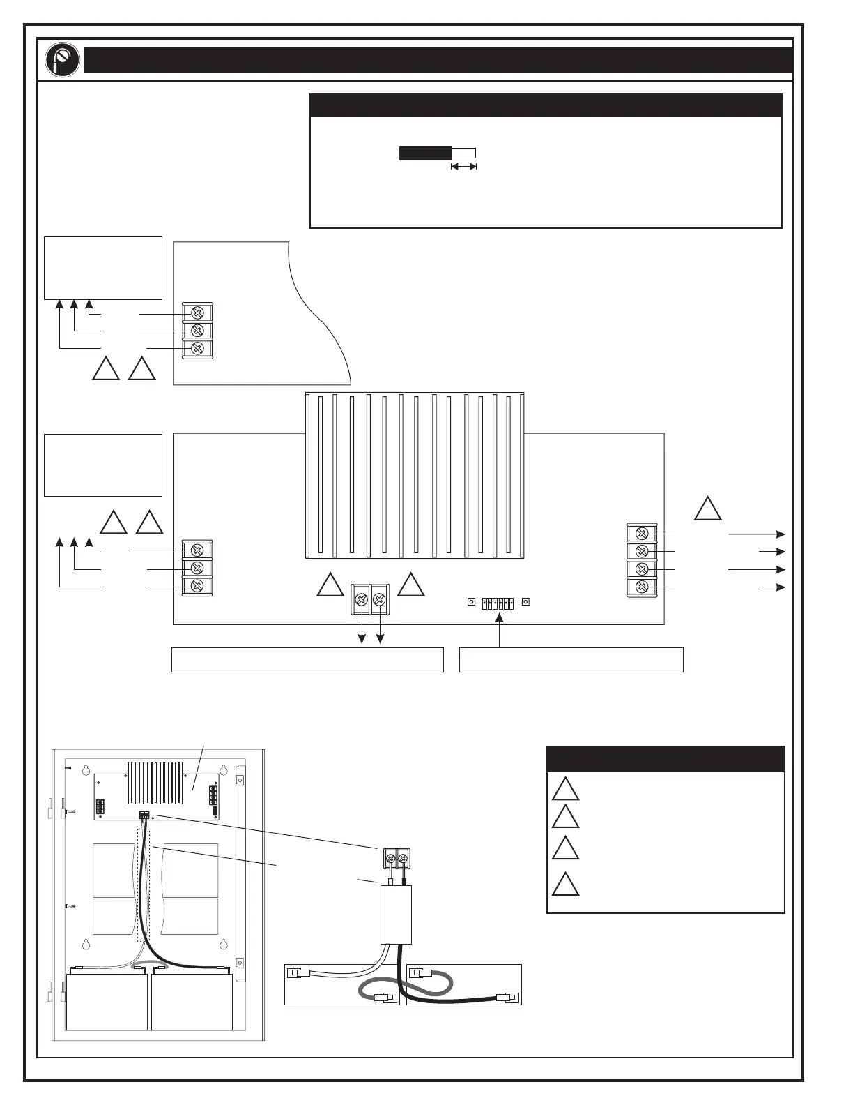
WIRING
Wire Stripping Guide
1/4 inch (6.4 mm)
Strip 1/4 inch from the ends of ALL wires that connect to the terminal blocks of the module.
Caution:
Exposing than 1/4 inch of wire may cause a ground fault.
Exposing than 1/4 inch of wire may result in a faulty connection.
more
less
L1
L2
G
TB1
24 Vdc
+
24 Vdc+
_
NAC2 power
NAC1 power
_
To dedicated 120 Vac,
15 Amp, 50/60 Hz
supervised branch
circuit
To dedicated 220 Vac,
7.5 Amp, 50/60 Hz
supervised branch
circuit
Ground
Line 1
Line 2
Hot
Neutral
Ground
220 Vac Primary Power Supply
120 Vac Primary Power Supply
See the details below for the battery terminal wiring.
See the ribbon cable connections in step 2.
Notes
Power-limited
Nonpower-limited
Supervised
Nonsupervised
1
1
2
2
2
2
3
4
4
4
3
387222.CDR REV 2.0 Page 2 of 2
Main
Controller
Module
Expander
Loop
Module
Route the battery wiring harness (P/N 250181)
through the plastic channel under the Main
Controller Module and the Expander Loop Module
to the battery terminals.
Battery
+
_
Top view
black wire
red wire
TB2
Battery
++
__
Battery
++
__
Plastic channel
Primary Power Supply
TB1
TB2
TB2
TB3
J1
BATTERY
Technical Manuals Online! - http://www.tech-man.com
 Loading...