DATE: 22AUG00
Related documentation: SAN-CPU installation sheet
INSTALLATION SHEET
INSTALLATION SHEET P/N: 3100029
REVISION LEVEL: 1.0
FILE NAME: 3100029.CDR
CREATED BY: B. Graham
APPROVED BY: K. Johnson
ISP96-2/ISP96-3
Annunciator/Switch Panel
PRODUCT DESCRIPTION
APPLICATIONS
SPECIFICATIONS
The ISP96 series multiplexed annunciator/switch panels
consist of metal face plate
that mounts to a 19-inch rack. Each LED/switch group
contains one switch and two LEDs. All LEDs and
switches are independently programmed and controlled.
The ISP96-2 LED/switch groups provide a two-position
toggle switch for every two LEDs. The up position
generates an active (off-normal) condition. The down
position is the normal state. Each LED requires one
output address. Each switch requires one input address.
The ISP96-3 LED/switch groups provide a three-position
toggle switch for every two LEDs. The up and down
positions will generate one of two active (off-normal)
conditions. The center position is the normal state.
Each ISP96 series panel interfaces with the rest of the
system through a dedicated SAN-CPU. It may use RS-
485, 20 mA, or Fiber optic communication formats. The
ISP96 panels are also fully compatible with regenerative
networks that use RS-485 lines.
48 LED/switch groups and a
ISP96 series panels provide a generic LED/switch matrix
for operator interface with the system. The panels may be
used for life safety functions, which require control and
annunciation. Such functions include, but are not limited
to:
HVAC control
Firefighter telephone circuits
Audio evacuation and paging systems
In HVAC applications, the switches function as HOA
(hand-off automatic) controls that override automatic
control of the system. HVAC controls include fans and
dampers. The LEDs indicate the status of the fans and
dampers, which use monitored limit switches and
run/stop contacts.
In firefighter telephone applications, the switches select
incoming calls. One LED will light to indicate that a circuit
is calling in. The other LED will light to indicate the circuit
has been connected to the master handset.
In audio evacuation and paging systems, the switches
allow the operator to control paging and silencing circuits.
The LEDs indicate the silenced or active status of the
speaker circuit.
Voltage
Standby current
Current per active LED
Fully loaded current
Temperature range
Humidity
Dimensions
24 Vdc
60 mA
6 mA, 268 mA total draw
680 mA
32 to 120 °F (0 to 49 °C)
85 % non-condensing
Height 5.25 in (13.3 cm)
Width 19 in (48.3 cm)
Depth 2 in (5 cm)
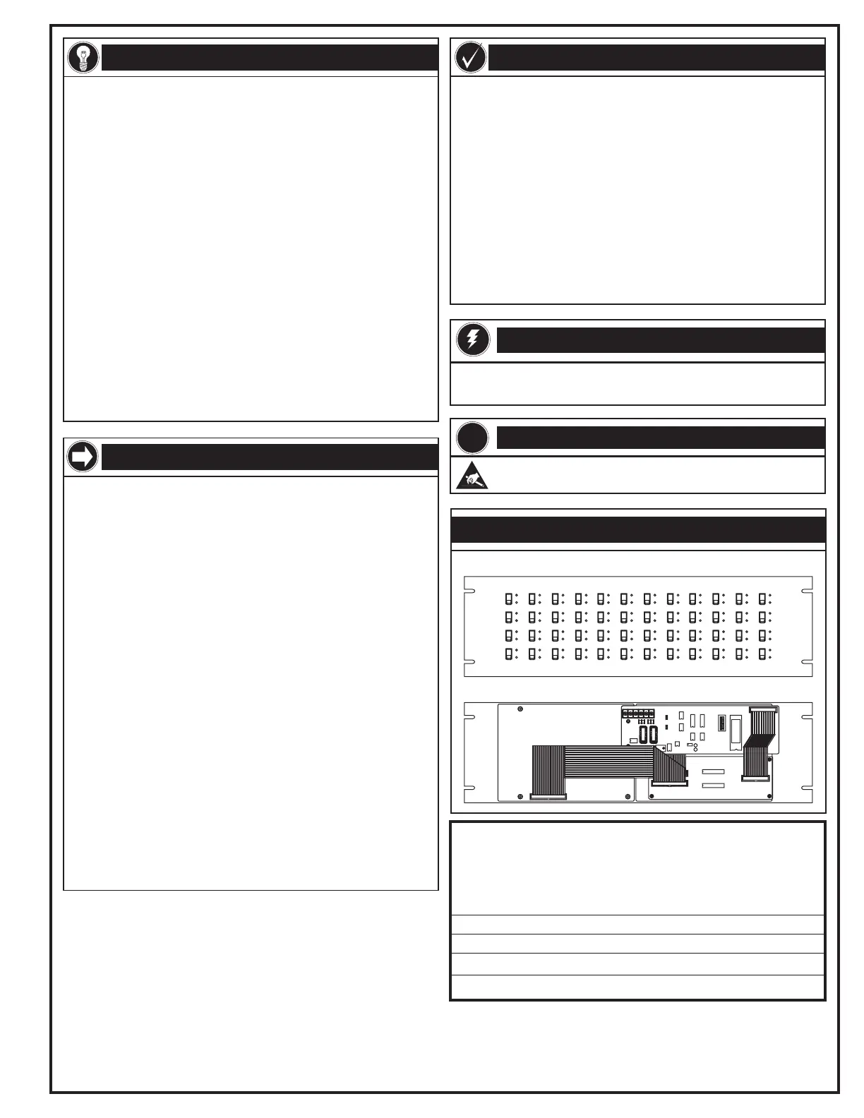
Front view
Rear view
Warning!
Disconnect power to cabinets before installing or removing components.
Failure to do so may result in serious injury or loss of life.
!
Caution!
Observe static-sensitive material handling practices.
EDWARDS SYSTEMS TECHNOLOGY, INC.
SARASOTA, FL: 941-739-4300 FAX 941-753-1806
CHESHIRE, CT: 203-699-3000 FAX 203-699-3075
OWEN SOUND, CANADA: 519-376-2430 FAX 519-376-7258
INTERNATIONAL, CANADA: 905-270-1711 FAX 905-270-9553
PRODUCT DIAGRAM
Technical Manuals Online! - http://www.tech-man.com
 Loading...