DATE: 24APR00
INSTALLATION SHEET:
INSTALLATION SHEET P/N: 270210
FILE NAME: 270210.CDR
REVISION LEVEL: 3.0
CREATED BY: B. Graham
APPROVED BY: B. Wanek
2-MCM
Main Controller Module
EDWARDS SYSTEMS TECHNOLOGY, INC.
SARASOTA, FL: 941-739-4300 FAX 941-753-1806
CHESHIRE, CT: 203-699-3000 FAX 203-699-3075
OWEN SOUND, CANADA: 519-376-2430 FAX 519-376-7258
INTERNATIONAL, CANADA: 905-270-1711 FAX 905-270-9553
PRODUCT DESCRIPTION
The Main Controller Module (MCM) is the foundation of the system
and contains the principal microprocessor and controls for the fire
alarm system.
The MCM has two dual purpose RS-485 ports. The RS-485 port
provides Class A (Style 6) or Class B (Style 4) communications for
the system. Each RS-485 terminal also provides communications
for 2-LSRAs, 2-SMDNs, and SAN Annunciators.
The MCM also has an RS-232 port to provide communications for
printers. A modular jack provides a means for downloading
programmed data from an IBM compatible computer to the MCM.
All external connections are transient-protected.
The MCM provides one multiplexed Signature Data Circuit (SDC)
and two Notification Appliance Circuits (NACs). The SDC and the
NACs can both operate on Class A or Class B wiring. The SDC
can support 96 Signature Series detectors and 94 Signature
Series modules. The NACs have separate input terminals, which
are rated at 24 Vdc @ 3.5 A or 100W@25Vrmsor70Vrms
audio. The NAC terminals may share power or receive it from an
external source.
During alarm, supervisory, and trouble conditions the MCM relay
contacts close to report the off-normal conditions. There are two
Form C relays and a Form A relay. The Form C relays handle
alarm and trouble conditions and operate on 24 Vdc, nominal @ 1
A. The Form A relay handles supervisory conditions and operates
on 24 Vdc, nominal @ 1 A.
The routing of power-limited and nonpower-limited wiring differs with
each cabinet. For more information on the routing of power-limited and
nonpower-limited wiring, see the cabinet’s installation sheet.
SPECIFICATIONS
Wire Stripping Guide
1/4 inch (6.4 mm)
Strip 1/4 inch from the ends of ALL wires that connect to the terminal
blocks of the module.
Caution:
Exposing than 1/4 inch of wire may cause a ground fault.
Exposing than 1/4 inch of wire may result in a faulty connection.
more
less
Warning!
Disconnect power to cabinets before installing or removing
components. Failure to do so may result in serious injury or loss of
life.
Input Power
RS-485 Terminals
*
*Note:
RS-232 Terminal
NACs
SDC
Relay Contacts
Environmental Conditions
24 Vdc @ 150 mA, standby; 275 mA active
Max. Line Capacity 30 addresses
Max. line parameters 0.44 f/100
Max. Wire Size 14 AWG (1.5 mm )
SAN annunciators, 2-LSRAs, 2-SMDNs, or 2-AACs.
Non-isolated, 50 ft. (15.2 m) max.
Must be located in the same room.
Quantity/Style Two Class A (Style Z) or Class B (Style Y)
Voltage 24 Vdc, Nominal
Available NAC Current 3.5 A for all NACs
NAC Current Rating 3.5 A or 100 W @ 25/70 Vrms per circuit
EOL Resistor 15 k , ½ W
Maximum Wire Size 12 AWG (2.5 mm )
Class (Style) Class A (Style 6) or Class B (Style 4)
Detector Capacity 96 Signature Series detectors
Module Capacity 94 Signature Series modules
Line Resistance 65 max. full load
Line Capacitance 0.33 f, max.
Maximum Wire Size 14 AWG (1.5 mm )
Alarm and Trouble Form C, rated at 24 Vdc nominal @ 1 A
Supervisory Form A, rated at 24 Vdc nominal @ 1 A
Temperature Range 32 to 120 °F (0 to 49 °C)
Humidity 0 to 93%, Non-condensing
mW
W
W
m
2
2
2
WIRE ROUTING
!
Caution!
Observe static-sensitive material handling practices.
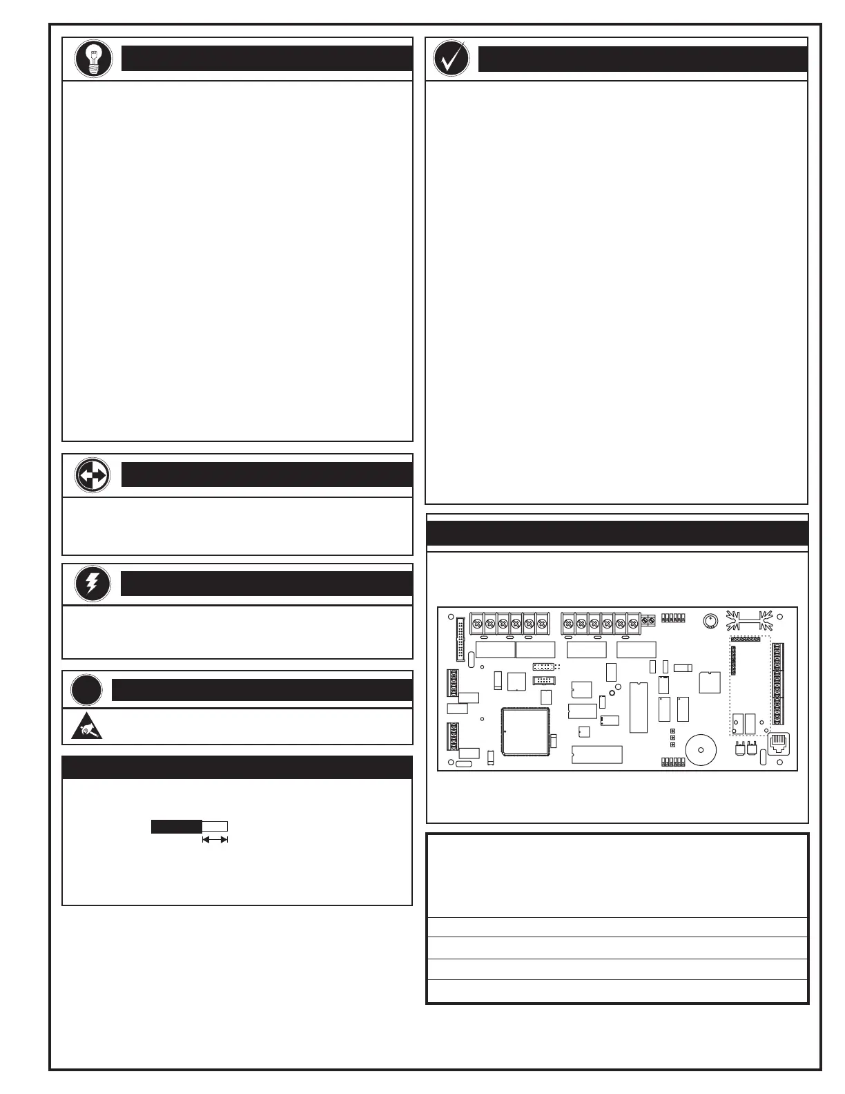
PRODUCT DIAGRAM
Related documentation: Installation and Service Manual
Technical Manuals Online! - http://www.tech-man.com
 Loading...