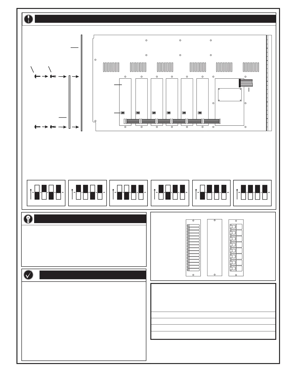
J2J2 J2J2 J2J2 J1J1 J1J1 J1J1
J3
J1
2-LCD
Inner door (rear view)
03
142
5
LED/switch
module
(rear view)
Dip switch
1 Mount the LED/switch modules.
Inner door (side view)
Plunger Grommet
LED/switch module
(side view)
ONON
11 22
33
44
ONON
11 22
33
44
ONON
11 22
33
44
03142
5
To
Main
Controller
Module
2
3
Connect the LED/Switch Module ribbon cables
Set the dip switches on the LED/switch modules.
1
2
3
Connect the ribbon cable from J3 on the 2-LCD to J1 on the first
module.
Connect the ribbon cable from J2 on the first module to the J1 on the
second module.
Repeat step 2 until you reach the last module.
Dip switch setting LED addresses Switch addresses
0 01-16 01-08
1 17-32 09-16
2 33-48 16-24
3 49-64 25-32
4 65-80 33-40
5 81-96 41-48
DATE: 21JUN00
Related documentation: 2-LCD installation sheet
INSTALLATION SHEET:
INSTALLATION SHEET P/N: 270214
REVISION LEVEL: 4.0
FILE NAME: 270214.CDR
CREATED BY: B. Graham
APPROVED BY: J. Massing
Front Panel LED(/Switch) Modules
PRODUCT DESCRIPTION
Models
2-12R4Y
2-16G
2-16R
2-16Y
2-8RY
Models
2-16G8S
2-16R8S
2-16Y8S
2-8GYS
2-8RYS
SPECIFICATIONS
The front panel LED/switch modules consist of 16 LEDs for point
annunciation. The LED/switch modules provide eight groups of two LEDs
combined with a switch. See the specifications for available LED color
options. The to each LED/switch identifies its
function. Communication with the Main Controller Module
is multiplexed using plug-in ribbon cables. Any
combination of three annunciator and switch modules may be mounted on
the panel's inner door. Blank Plates (model 2-FBP) fill unused inner door
spaces.
individual
protected slip-in label next
requires no point
to point wiring, because it
LED/switch options
Model Description
Blank plate option
Switches
Temperature range
Humidity range
2-16G 16 green LEDs
2-16R 16 red LEDs
2-16Y 16 yellow LEDs
2-16Y8S 16 yellow LEDs and 8 switches
2-8GYS 8 green / 8 yellow alternating LED/switch pairs
2-FBP
Momentary push button
32 to 120 F (0 to 49 C)
0 to 93%, non-condensing
2-12R4Y 12 red LEDs over 4 yellow LEDs
2-16G8S 16 green LEDs and 8 switches
2-16R8S 16 red LEDs and 8 switches
2-8RY 8 red LEDs over 8 yellow LEDs
2-8RYS 8 red / 8 yellow alternating LED/switch pairs
°°
INSTALLATION
Note: White indicates the correct dipswitch position.
2-FBP
EDWARDS SYSTEMS TECHNOLOGY, INC.
SARASOTA, FL: 941-739-4300 FAX 941-753-1806
CHESHIRE, CT: 203-699-3000 FAX 203-699-3075
OWEN SOUND, CANADA: 519-376-2430 FAX 519-376-7258
INTERNATIONAL, CANADA: 905-270-1711 FAX 905-270-9553
Note: Do not try to insert
the plunger and grommet
into the mounting holes
at the same time. Insert
the grommet first and
then the plunger to avoid
damaging them.
Technical Manuals Online! - http://www.tech-man.com
 Loading...