DATE: 30MAR00
Related documentation: Installation and Service Manual
INSTALLATION SHEET:
INSTALLATION SHEET P/N: 387345
REVISION LEVEL: 2.0
FILE NAME: 387345.CDR
CREATED BY: B. Graham
APPROVED BY: J. Massing
2-AAC
Audio Control Module
PRODUCT DESCRIPTION
SPECIFICATIONS
Power requirements
Frequency response
Output
Auxiliary inputs
Supervision
Internal Generator tones
Environmental conditions
Power 24 Vdc
Standby with 2-MIC 75 mA
Standby with 2-TEL 75 mA
Active with 2-MIC 110 mA
Active with 2-TEL 120 mA
400 Hz to 4 kHz
Level 1.0 Vrms
Distortion < 3%
Wiring configuration 2 channels, Class B (Style Y) or
Class A ( Style Z)
Maximum load 15 SIGA-AAxx amplifiers
Maximum resistance 100
Maximum capacitance 0.2 F
Maximum wire size 14 AWG (1.5 mm )
Configuration 2 electrically isolated channels
(selected via programming)
Input impedance 10 K
Input level 0.5 to 1.75 Vrms
Audio output (dc) 47K EOL
Audio output (ac) Audio pulse
Internal 1 kHz ac audio pulse
Communication Internally through RS-485 data
Maximum wire size 14 AWG (1.5 mm )
Slow whoop
Fast whoop
1 kHz steady
1 kHz march time
1 kHz Morse U
Hi-Lo
Chime
Horn
Low tone
Hi-Lo horn
Fast Hi-Lo horn
Temporal (3-3-3)
4-4 code
1kHz@20bpm
1 kHz @ 120 bpm
Temperature 32 to 120 °F (0-49 °C)
Humidity 0 to 93%, non-condensing
W
m
W
W
2
2
INSTALLATION
Warning!
Disconnect power to cabinets before installing or removing
components. Failure to do so may result in serious injury or loss of
life.
!
Caution!
Observe static-sensitive material handling practices.
Primary Power Supply
Main Controller Module
Expander Loop Module
Audio Control Module
Note: See the installation sheets of the following wallboxes for other
locations to mount the Audio Amplifier:
WB3(R)
WB7(R)
RACCR
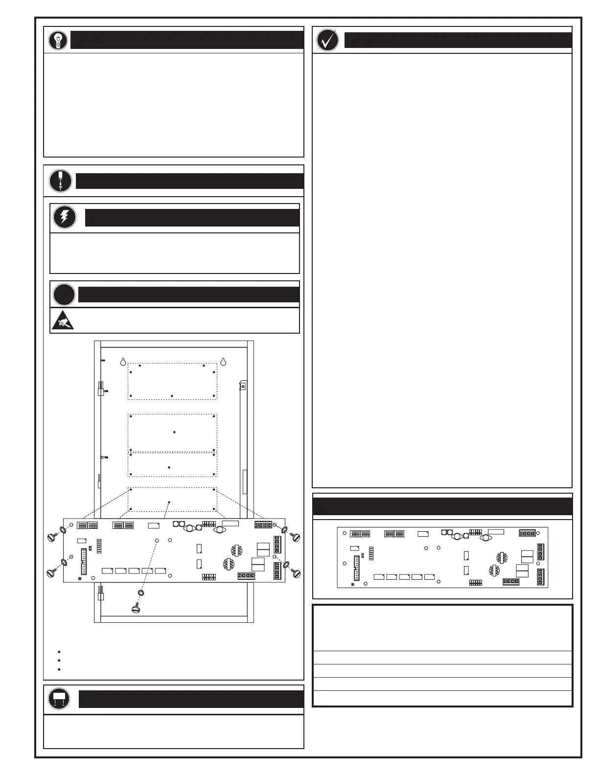
Jumper Settings
Leave JP1 installed in the absence of a 2-TEL Firefighter Telephone.
The removal of JP1 enables supervision for the 2-TEL option board.
PRODUCT DIAGRAM
EDWARDS SYSTEMS TECHNOLOGY, INC.
SARASOTA, FL: 941-739-4300 FAX 941-753-1806
CHESHIRE, CT: 203-699-3000 FAX 203-699-3075
OWEN SOUND, CANADA: 519-376-2430 FAX 519-376-7258
INTERNATIONAL, CANADA: 905-270-1711 FAX 905-270-9553
Audio
Control
Module
The Audio Control Module is a dual channel electronics package, which
interfaces with the paging microphone operator interface (2-MIC) and
the firefighter telephone (2-TEL). Two integral tone generators provide
alert and evacuation signaling. Two auxiliary pre-amp level (1 V) inputs
handle pre-recorded messages or other external sources. Each of the
two audio output channels has a Class B or Class A, pre-amp level (1
V) output, to feed the audio amplifiers.
The Audio Control Module mounts on the rear of the enclosure and
provides terminals for the external audio inputs, two audio risers, and
RS-485 data.
Technical Manuals Online! - http://www.tech-man.com
 Loading...