DATE: 17APR00
INSTALLATION SHEET
INSTALLATION SHEET P/N: 3100023
REVISION LEVEL: 1.0
FILE NAME: 3100023.CDR
CREATED BY: B. Graham
APPROVED BY: R. Wolf
CDR-3 Bell Coder
PRODUCT DESCRIPTION
SPECIFICATIONS
The CDR-3 Coder is a microcomputer-based module that provides
coded outputs in response to alarm conditions. The CDR-3 is used with
systems that require either march time, temporal, or unique coded
outputs for separate zones. The CDR-3 decodes alarm codes
embedded in printer messages that it receives through its RS-232
input.
Input voltage
Standby current
Alarm curren
Supervised tone outputs (isolated)
Tone outputs
Dry contact (coded output)
PSNI Queue
RS-232 Input baud rates
24 Vdc
60 mA
t 100 mA
Output impedance 1.2 k
Output voltage 3.5 Vrms
EOL 10 k
Temporal March time (60 or 90 bpm)
@ 1kHz, 10 Vrms
Coded 1 kHz @ 10 Vrms
Output rating 30 Vdc @ 4 A max (Pf .35),
25 Vrms @ 100 W max,
70 Vrms @ 100 W max
March-time 60 or 90 bpm
Normal coding range 4 rounds, 1-4 digits, 0-9 each
Extended digit range 3 rounds, 1-3 digits, 1 digit
0-15, 2 digits 0-9 each
50 most recent alarms
600, 1200, 2400, 4800
W
W
Installation
Maximum wire size
1/2 footprint mounting studs
14 AWG
(1.5 mm )
2
WARNINGS
INSTALLATION INSTRUCTIONS
This module will NOT operate without electrical power. As fires
frequently cause power interruption, we suggest you discuss further
safeguards with your local fire protection specialist.
Disconnect power before installing or removing the module.
Dangerous voltages may be present at terminals even when power
is disconnected.
NOTES
If a printer and a CDR-3 are connected to the system:
Program both devices as enabled.
•
•
•
Connect both devices in parallel or to separate ports (if available).
Program the same baud rate for both devices when they share the
same port.
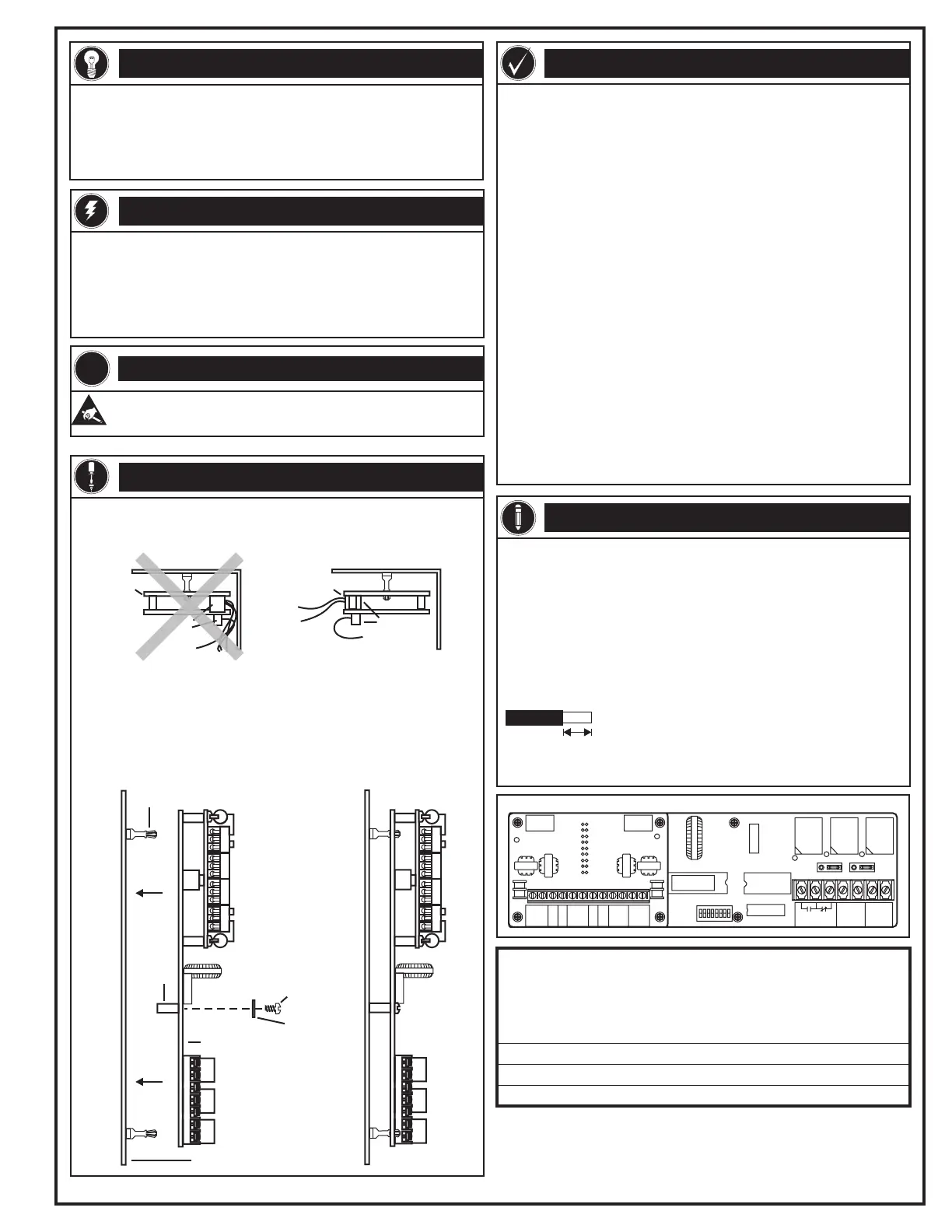
Snap-top standoff
Enclosure
Main board
Screw
Washer
Plastic
spacer
To mount the CDR-3:
1. Secure the plastic spacers to back of the main board with the
screws and washers provided.
2. Snap the main board onto the snap-top standoffs of any half
footprint in the enclosure.
Note: Mount the CDR-3 so that its terminal blocks do not face the corner
of the enclosure. Terminal blocks must face out for wiring to be installed
and removed easily.
Terminal
blocks
Terminal
blocks
Wiring is difficult to
install and remove.
Wiring is easy to
install and remove.
CDR-3CDR-3
Enclosure Enclosure
!
Caution!
Observe static-sensitive material handling practices.
1/4 inch (6.4 mm)
Strip 1/4 inch from the ends of ALL wires that connect to the terminal
blocks of the module.
Exposing than 1/4 inch of wire may cause a ground fault.
Exposing than 1/4 inch of wire may result in a faulty connection.
more
less
Printer connections
Wire stripping
EDWARDS SYSTEMS TECHNOLOGY, INC.
SARASOTA, FL: 941-739-4300 FAX 941-753-1806
CHESHIRE, CT: 203-699-3000 FAX 203-699-3075
OWEN SOUND, CANADA: 519-376-2430 FAX 519-376-7258
INTERNATIONAL, CANADA: 905-270-1711 FAX 905-270-9553
Technical Manuals Online! - http://www.tech-man.com
 Loading...