P/N: 3100023 REV: 1.0 Page 2 of 2
DIP SWITCH SETUP
Temporal Tone On On On [1]
March Tones
Fast (90 beats per minute) Off [2]
Slow (60 beats per minute) On [2]
Code Operations
Normal 4-digit code [1] Off Off
Extended first digit (adds digits 1 and 2) On Off
Extended second digit (adds digits 2 and 3) Off On
Extended third digit (adds digits 3 and 4) On On
Baud Rates [3]
600 Off Off
1200 On Off
2400 (default) Off On
4800 On On
Systems
CCS-1 On
All other systems Off
[1] [1] [1] [1]
[1] [1] [1] [1] [1] [1]
[1] [1] [1] [1] [1] [1]
[1] [1] [1] [1] [1]
[1] [1] [1] [1] [1] [1]
[1] [1] [1] [1] [1] [1]
[1] [1] [1] [1] [1] [1]
[1] [1] [1] [1] [1] [1]
[1] [1] [1] [1] [1] [1]
[1] [1] [1] [1] [1] [1]
[1] [1] [1] [1] [1] [1]
[1] [1] [1] [1] [1] [1] [1]
[1] [1] [1] [1] [1] [1] [1]
Function DIP Switch Position
12345678
Mode of Operation Input Output Code
Normal operation 1234 1234 Digit 1, Digit 2, Digit 3, Digit 4
Extended first digit 1234 0334 0, (Digit 1 + Digit 2), Digit 3, Digit 4
Extended second digit 1234 0154 0, Digit 1, (Digit 2 + Digit 3), Digit 4
Extended third digit 1234 0127 0, Digit 1, Digit 2, (Digit 3 + Digit 4)
Code Format
For unique alarm codes, each digit can be any value
between 0 and 9.
For extended digits, the two added digits may be any
values that, when added, equal the desired value.
If the sum of two digits is greater than 15, use a value of 15.
For a zero, insert a pause in the tone sequence.
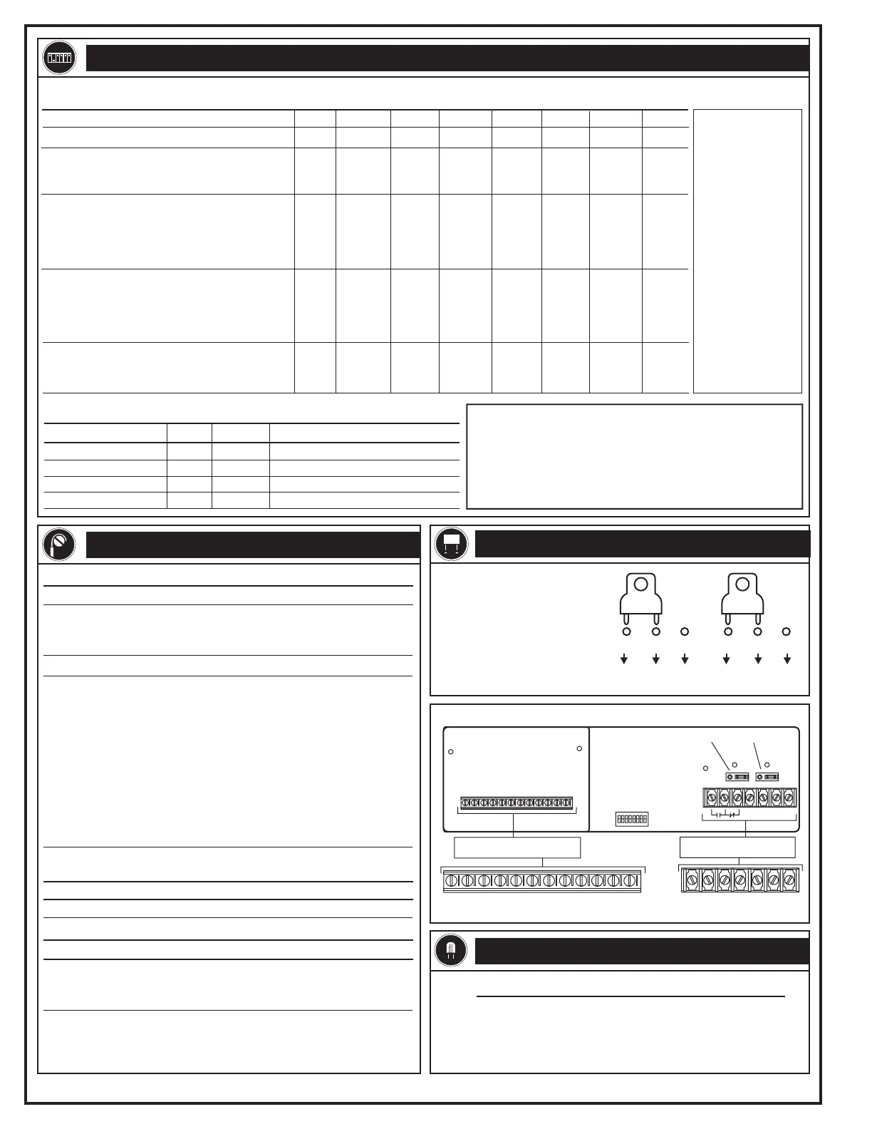
Connector Name* Function
TB1 connectors: main board
TB1 connectors: daughter board
(Figure 1)
1-3 DURATION Duration relay contacts
4, 5 TEMPORAL March time code output contacts
6, 7 BELL CODE Coded output contacts
1, 2 TEMPORL TONE March time or temporal tone output
signal (10 k EOL required)
3 EARTH GRND Earth ground
4 24V + 24 Vdc power input
5, 6 COMMON DC Common
7 RS232 INPUT RS-232 input
8 PRINT SUPV Printer supervision
9, 10 TRBL OUT Module trouble relay
(contacts close on trouble)
11, 12 CODED TONE Coded tone output (10 k EOL
required)
(Figure 1)
W
W
*Names are listed here exactly as they appear on the board.
INTERNAL WIRING
The CDR-3 provides two relay
jumpers: JP1 and JP2. JP1 sets
Bell Code relay contacts to
either normally open (NO) or
normally closed (NC). JP2 sets
the Temporal relay contacts to
either NO or NC. See Figure 1
for the locations of JP1 and JP2.
JUMPER SETUP
TB1-1 through TB1-12
Daughter board Main board
TB1-1 through TB1-7
JP1
JP1
JP2
JP2
D3
D5
D1
D2
D4
DIP switch
Figure 1: CDR-3 terminals, LEDs, and dip switches
1
234567
1
2 3 4 5 6 7 8 9 10 11 12
LED Color Status
D1 Red Bell code relay active
D2 Red Temporal relay active
D3 Red Duration relay active
D4 Yellow Module trouble
D5 Green Power on
LEDs
Terminal wiring types: main board
Wiring types TB1 connectors
Power-limited* 1-7
Terminal wiring types: daughter board
Wiring types TB1 connectors
Earth ground 3
Power-limited* 4, 5, 6, 9, 10
Supervised, power-limited 1, 2, 7, 8, 11, 12
*Use power-limited wiring if the source is power-limited. If the source is
nonpower-limited, maintain a space of 1/4 inch from power-limited
wiring. Otherwise, use FPL, FPLP, FPLR, or an equivalent in
accordance with the National Electric Code.
COMCOM NCNC NONO
To TB1-6, TB1-7
main board
To TB1-4, TB1-5
main board
[1] indicates that
the DIP switch
does not apply to
the function.
[2] The On position
configures the
CDR-3 to generate
march tones upon
the receipt of an
alarm signal. The
Off position
configures the
CDR-3 to generate
march tones upon
power-up.
[3] Program the
CDR-3 and the
RS-232 to the
same baud rate.
Technical Manuals Online! - http://www.tech-man.com
 Loading...