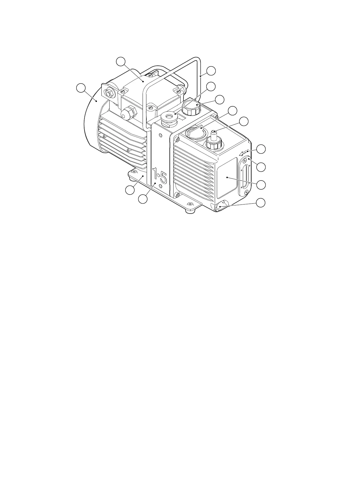
Figure 1 General view of the pump
CS/1128/A
7
6
5
3
2
4
12
11
10
9
8
13
1
1. Fan cover 2. Motor terminal box
3. Handle (can be removed: see Locate the
pump on page 18)
4. NW10 inlet-port (adaptor ange)
5. Gas-ballast control
6. Oil ller-plug 7. Outlet nozzle
8. Pump/motor sha rotaon direcon
arrow
9. Oil sight-glass and bezel
10. Pump idencaon label
11. Oil drain-plug 12. Removable side panel
13. Baseplate
2.4 Gas-ballast
To pump high vapour loads, gas-ballast is delivered into the pump to prevent
condensaon of the vapour carried by the pumped gases.
Air (or another gas) can be introduced into the low vacuum stage through the gas-ballast
control. The gas-ballast control is a mul-turn valve which can be adjusted, as required,
between closed and fully open.
Page 11
A37132880_F - Introducon