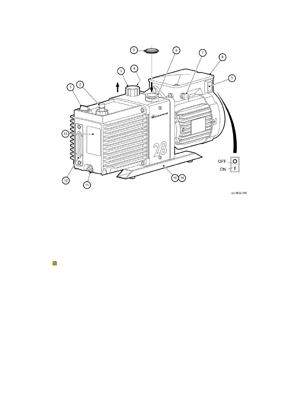
Figure 1 General view of the pump
1. Oil ller 2. Outlet nozzle
3. Gas-ballast control 4. Gas-ballast inlet
5. Centring-ring and O-ring (supplied) 6. Inlet-port (adaptor ange)
7. Cable-gland/Amphenol connector
posion
8. Motor terminal box
9. On/O switch
10. Box secon skids 11. Oil drain-plug (gravity drain)
12. Oil sight-glass 13. Pump idencaon label
14. Oil drip tray
Note:
A pump with a single-phase motor is shown in this gure. The motor shown in this gure
is not representave of the motor used on the E2M28 (Amphenol) pump with item
number A37317984. On this pump, cable-gland/amphenol connector posion and on/o
switch are transposed, with cable-gland/amphenol connector posion being an
IEC60320 16-20 Amp socket.
2.4 Gas-ballast
To pump high vapour loads, gas-ballast is delivered into the pump to prevent
condensaon of the vapour carried by the pumped gases.
Air (or another gas) can be introduced into the low vacuum stage through the gas-ballast
control. The gas-ballast control is a mul-turn valve which can be adjusted, as required,
between closed and fully open.
Page 11
A37310880_V - Introducon