© Edwards Limited 2007. All rights reserved. Page 11
Edwards and the Edwards logo are trademarks of Edwards Limited.
Installation
D374-20-880 Issue E
3.4 Parallel Interface Connections
Note: Refer to Section 4 to determine the signals used in the parallel cable.
1. Make a suitable parallel cable. Refer to Section 8 for back shell kits if required.
2. Connect one end of the parallel cable to your control equipment.
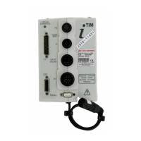
3. Refer to Figure 1. Fit the socket at the other end of the cable to the appropriate connector on the iTIM.
3.5 Serial Interface Connections
1. Ensure that your control equipment is correctly configured (for example, install the necessary software) to
interpret your commands, to send and receive messages to and from the iTIM, and to display information
received from the iTIM.
2. Ensure that the serial settings of your control equipment are configured correctly for the iTIM: refer to the
information given in Section 4.
3. Make a three-wire RS232 cable to connect your control equipment to the iTIM: Table 2 shows the serial interface
connection signals and Table 3 shows the example IBM PC-compatible connections. If the cable between your
control equipment and the iTIM is more than 10m long, you must incorporate line drivers in the cable. When you
make the cable:
z Fit a 9-way male ‘D-type’ plug on one end of the cable.
z Fit a connector suitable for the serial connector on your control equipment to the other end of the cable.
Typically, this will be a 9-way female ‘D-type’ connector, to fit the COMM port of your PC.
4. Refer to Figure 1. Fit the 9-way ‘D-type’ plug on one end of the RS232 cable to the serial connector (7) on the
iTIM; fit the connector on the other end of your RS232 cable to the appropriate connector on your control
equipment.
Table 2 - Serial Interface Connections
Signal Serial Connector (9-way ‘D-type’ plug) Direction
RXD Pin 2 Output
TXD Pin 3 Input
GND Pin 5 -
Table 3 - Example IBM PC-Compatible Serial Connections
Signal
Serial Connector
(9-way ‘D-type’ plug)
IBM PC compatible connectors
9-way ‘D-type’ male 25-way ‘D-type’ male
RXD Pin 2 Pin 2 Pin 3
TXD Pin 3 Pin 3 Pin 2
GND Pin 5 Pin 5 Pin 7