© Edwards Limited 2013. All rights reserved. Page 35
Edwards and the Edwards logo are trademarks of Edwards Limited.
Installation
B800-00-880 Issue D
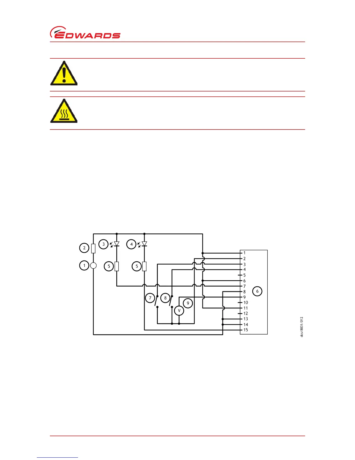
Refer to Figure 11 for a schematic diagram of the logic interface connections.
The electrical supply for the nEXT pump must meet the requirements of BS EN 61010-1 / C22.2 1010-1. Ensure that
hazardous voltages as defined in EN61010 cannot be present on the electrical interface to the nEXT pump.
The nEXT pump 0 V is not referenced to earth (ground). Ensure that there is only one path between 0 V and earth.
Multiple connections between 0V and earth must be avoided in order to avoid unexpected offset voltages on control
and status signals and possible problems with serial communications. If no other connection is present between 0 V
and earth, the connection should be made at the power supply. Be aware that other electrical equipment connected
to the system could introduce a connection between 0 V and earth, for example a personal computer or measuring
equipment.
Refer to Table 11 - logic interface connector pins when connecting the electrical supply to the customer connector
mating half.
Figure 11 - Logic interface connections - parallel control
Note: The pump controller may be supplied from voltages above 24 V as specified in Table 10, however the
circuitry connected to the normal and fail lines must still respect the maximum external pull up voltage
rating given in Table 10.
Do not exceed the maximum supply voltage. Excessive supply voltage will cause permanent
damage to the control electronics and may result in a mechanical hazard in some failure
conditions.
When connecting the nEXT pump to the power supply, ensure that all 3 pins for the 24 - 48 V
connection and all 3 pins for the 0 V connection on the customer connector mating half are
connected to the power supply.
1. 24 V d.c. electrical supply
2. Fuse
3. Optional LED indicator - system OK
4. Optional LED indicator - normal speed
5. Current limit resistor for LED
6. nEXT pump logic interface
7. Start switch
8. Optional standby switch
9. Optional voltmeter
to monitor analogue output