STP-301/451 Series Instruction Manual
6-13
Installation
3) Connecting the Power (Primary Side) Cable
Connect the power cable to the "AC POWER CON1" on the STP control unit rear panel as
shown in Table 6.1.
Secure the power cable connector using the cable fitting tool. (see Figure 6.11)
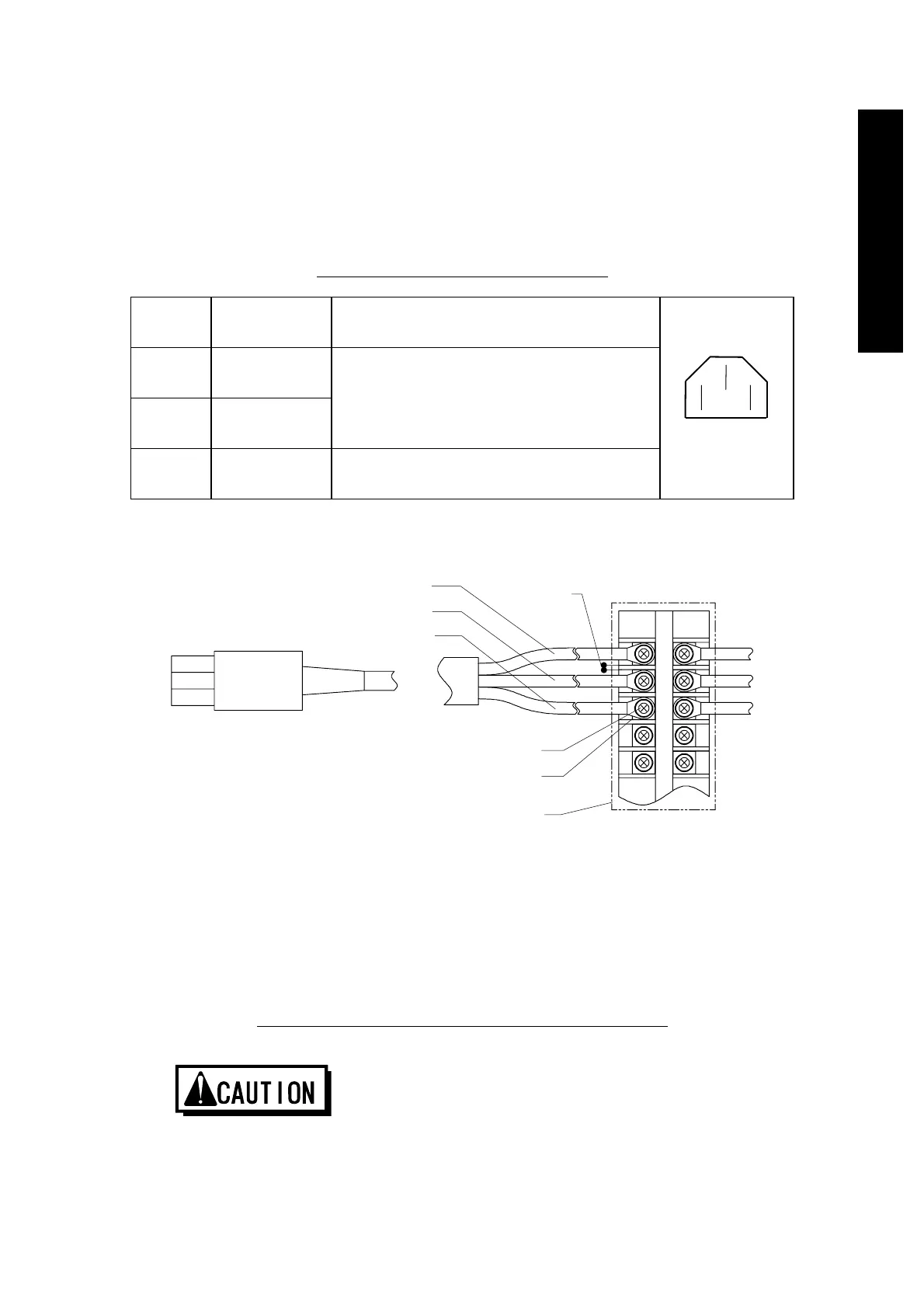
Table 6.1 Connecting the Power Cable
CON1
Pin No.
Cable Color Remarks
L Brown
N Blue
Single phase 200 to 240 V AC +/-10%
(for 200 V specification)
Single phase 100 to 120 V AC +/-10%
(for 100 V specification)
Both 50/60 Hz
PE Yellow/Green Ground
L PE N
Rear Panel
“AC POWER CON1”
Outline of connector
L
N
G
*1
Use the UL-recognized terminal block satisfying with the following conditions;
a) Clearance (between each terminal) : 1.5mm or more
b) Material flammability: UL 94V-0
c) The installation category ∐.
*2
Use material flammability: UL 94V-0
Figure 6.10 Connecting Method of the AC Power Cable
◇ Confirm the power voltage on the name plate.
◇ Connect the primary power cable securely to prevent incorrect wiring.
◇ DO NOT apply surge voltage exceeding 1kV to the input power line.
◇ Always ground the primary power cable to prevent electric shock.
Power unit side Power supply side
(Primary side)
Br
n
Yellow/Green
Blue
Clearance
M4-bolt
fixin
screw
Crimp-type terminal (M4)
Cover
*2
 Loading...

