PD00E0XKNXFI00020100_HANDBOOK_EN.DOCX
PD00E0xKNX KNX PRESENCE DETECTORS RANGE Handbook
Eelectron SpA, Via Monteverdi 6,
I-20025 Legnano (MI), Italia
Tel: +39 0331.500802 Fax:+39 0331.564826
E-mail: info@eelectron.com Web:www.eelectron.com
C.F. e P.IVA 11666760159
Tribunale di Milano 359157-8760-07
CCIAA Milano 148549
Measured value ceiling
PT1 [*10 Lux]
Measured value desk
PT1 [*10 Lux]
Measured value ceiling
PT2 [*10 Lux]
Measured value desk
PT2 [*10 Lux]
To set the correct values of the parameters, use a
lux meter to detect the brightness and follow the
procedure described below; if possible, carry out the
procedure in the dark hours or with the shutters
down, in any case avoid situations in which the
external light enters the room directly because in
this case the result could be distorted.
Place the lux-meter on the work surface for which
you want to have accurate brightness control,
Change the brightness of the lamps until you get the
lighting value lower than the desired one: if for
example the desired value is 500 Lux, modulate the
lighting up to read 100/200 Lux on the lux-meter
placed on the desk.
Read the brightness value measured by the sensor
and available on object 8 <Illuminance> Output
Set in ETS the parameter "Value measured on the
ceiling PT1" with the value sent by the sensor
(divided by 10) and the parameter "Value measured
on the desk PT1" with the value measured by the
lux-meter (divided by 10)
Change the brightness of the lamps until obtaining
the lighting value higher than the desired one:
considering a desired value of 500 Lux, modulate the
lighting up to read 700/900 Lux on the lux meter
placed on the work surface.
Read the brightness value measured by the sensor
and available on object 8 <Illuminance> Output
Set in ETS the parameter "Value measured on the
ceiling PT2" with the value sent by the sensor
(divided by 10) and the parameter "Value measured
on the desk PT2" with the value measured by the
lux-meter (divided by 10)
Very fast
fast
normal
slow
very slow
Defines the response speed of the controlled output after
a measured ambient brightness variation (see figure 1)
Minimum output value
[*10 Lux]
Maximum output value
[*100 Lux]
Values below the minimum value will be forced to the
minimum value, values greater than the maximum value
will be forced to the maximum value,
Minimum difference in the measurement in Lux
compared to the previous value which triggers the
immediate sending of the value
No cyclic sending, 15 s .. 12 h
Period of cyclical sending of the illuminance
measurement
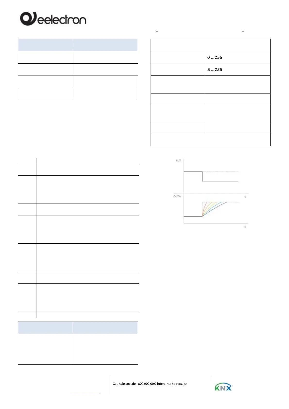
AVERAGE LUX CALCULATION ALGORITHM (Fig. 1)
When there is a sudden change in illuminance (in
the example the lux are reduced) the system reacts
by increasing the control value%, the red slope
corresponds to the "very fast" algorithm, the purple
one (softer) corresponds the "very slow" algorithm.
8. Remote presence
The sensor can also receive presence information
from other sensors (remote sensors) which therefore
act as "slaves" of the main sensor acting as "master".
The "slave" sensors are used to increase the
detection area. When a sensor acts as a "slave" it can
still also act as a "master" for the area it covers.
The settings relating to the management of the
slaves can be set in the "Remote Presence" section.
The device can receive up to 4 x 1-bit telegrams on
4 different addresses from "slave" sensors, for each