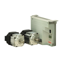
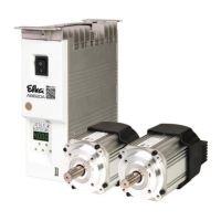
EFKA DA320G5351
27
Supplier Level
Code no. 311 with control operation
Code no. 3112 with control panel operation
Parameter Designation Unit Limits Preset for Ind.
max min 100Ω 220Ω 680Ω 1000Ω
246 in7 Selection of input function on socket A/9 for 69 0 27 27 27 27 A
input 7
0 = No function
All other functions of the keys as with parameter 240
247 in8 Selection of input function on socket A/10 for 69 0 26 26 26 26 A
input 8
0 = No function
All other functions of the keys as with parameter 240
248 in9 Selection of input function on socket A/13 for 69 0 23 23 28 23 A
input 9
0 = No function
All other functions of the keys as with parameter 240
249 i10 Selection of input function on socket A/14 for 69 0 17 17 17 17 A
input 10
0 = No function
All other functions of the keys as with parameter 240
250 FmA Function modules for output A on socket A/30 14 0 0 1 1 1 A
and input A on socket A/8 active only if
parameter 255 is not equal to 10.
0 = No function
1 = Switch stitch length
2 = Fullness control with speed limitation
3 = Fullness control without speed limitation
4 = Single stitch with stitch length switching
5 = Lift / lower roller
6 = Lift / lower fabric endstop
7 = Thread tension reduction
8 = Manual edge trimmer
9 = Automatic edge trimmer
10 = Triflex function: affects stitch length, thread
tension, speed limitation, automatic backtack
and function module for output B
(parameter 255 = 7)
11 = High lift for walking foot
12 = Functions of sewing foot pressure reduction:
the following functions are available if the key
is enabled:
- Pedal 0 Pulsing parameter 334 is
effective
- Pedal >1 Pulsing parameter 334 is
effective
- Pedal +1 Sewing foot is lowered
- Pedal –1 Pulsing parameter 204 is
effective
- Pedal –2 Pulsing parameter 204 or
trimming operation is effective
13 = Handwheel runs in the direction of rotation
according to setting of parameter 161
14 = Handwheel runs in the opposite direction of
rotation according to setting of parameter 161
251 AFA Output A (A/30) and LED A (A/29) after thread 1 0 0 0 0 0 A
trimming
0 = Output signals are maintained as before
thread trimming
1 = Output signals as after power On
Function with pa. 250 = 1, 2, 3, 7, 8, 9, 10
252 Ain Output A (A/30) 1 0 0 0 0 0 A
0 = Output not inverted
1 = Output inverted
 Loading...