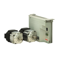
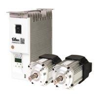
EFKA DA320G5351
29
Supplier Level
Code no. 311 with control operation
Code no. 3112 with control panel operation
Parameter Designation Unit Limits Preset for Ind.
max min 100Ω 220Ω 680Ω 1000Ω
262 hPt 0 = Roller remains lowered when enabling 1 0 0 0 1 0 A
high lift for walking foot.
1 = Roller is lifted when enabling high lift for
walking foot.
Effective only if parameter 250 = 11 and
parameter 255 = 5 or if parameter 250 = 5 and
parameter 255 = 11.
263 ihr Handwheel increments carried out when incr. 500 0 10 10 10 10 A
the key is pressed once (function module
A at the input of socket A/8 or function
module B at the input of socket A/7)
264 nhr Handwheel speed RPM 150 30 50 50 50 50 A**)
265 dhr Delay time until the key is pressed down ms 2550 0 200 200 200 200 A**)
causing the handwheel to rotate
continuously (function module A at the
input of socket A/8 or function module B
at the input of socket A/7).
Pressing the key briefly: if ≤ preset value
of parameter 262. Increments set using
parameter 260 are carried out.
Keeping the key pressed down: if ≥
preset value of parameter 262. Handwheel
rotates continuously.
266 LFL 0 = Sewing foot lowers when the handwheel 1 0 1 1 1 1 A
rotates.
1 = The functions “pedal in pos. –1” or “automatic
sewing foot lift” remain effective
267 kFk 0 = The edge trimmer remains On, independently 1 0 0 0 0 0 A
of sewing foot lifting.
1 = The edge trimmer is disabled when the
sewing foot is lifted
269 PSv Positioning shift degrees 100 0 15 15 15 15 A
270 PGm Selection according to the position sensors. 5 0 0 0 0 0 A
Setting of socket B18 see chapter “Connection
Diagram”
0 = The positions are generated by means of the
transmitter incorporated in the motor and can
be set using parameter 171.
1 = Setting the sensor to position 2.
Set position 1 using parameter 171, starting
from leading edge position 2.
2 = Setting the sensor to position 2.
Set position 1 using parameter 171, starting
from trailing edge position 2.
3 = Setting the sensor to position 1.
Set position 2 using parameter 171, starting
from leading edge position 1.
4 = Setting the sensor to position 1.
Set position 2 using parameter 171, starting
from trailing edge position 1.
5 = No position sensor available. The drive stops
unpositioned. The thread trimmer function is
suppressed with this setting.
**) When programming the 3-digit or 4-digit control parameter values (without control panel), the 2-digit or 3-digit
value displayed must be multiplied by 10.
 Loading...