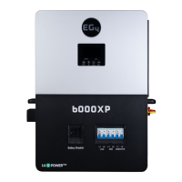
9
CAUTION: It is required to use a PV surge protection device. Damage to the inverter can occur from surges
such as lighting or short circuits.
Model Typical Amperage Cable Size Torque
6KW 27A 10AWG ~17-21 in-lbs (-2.0-2.4Nm)
PV Module Selection:
1. Open Circuit Voltage (Voc) of the PV modules/strings must not exceed the unit's maximum rating. Voc
must be calculated including the environmental impacts, such as temperature in accordance to the
module manufacturer's data sheet and reliable weather data for the installation location.
2. Voltage at Maximum Power (Vmp) of PV strings must be higher than the start-up voltage of the inverter.
WARNING: Exceeding the maximum input voltage will destroy the unit!
Solar Charging Mode
INVERTER MODEL 6KW
Max. PV Array Open Circuit Voltage 500 Vdc
PV Array MPPT Voltage Range
120-480Vdc
MPP Number 1
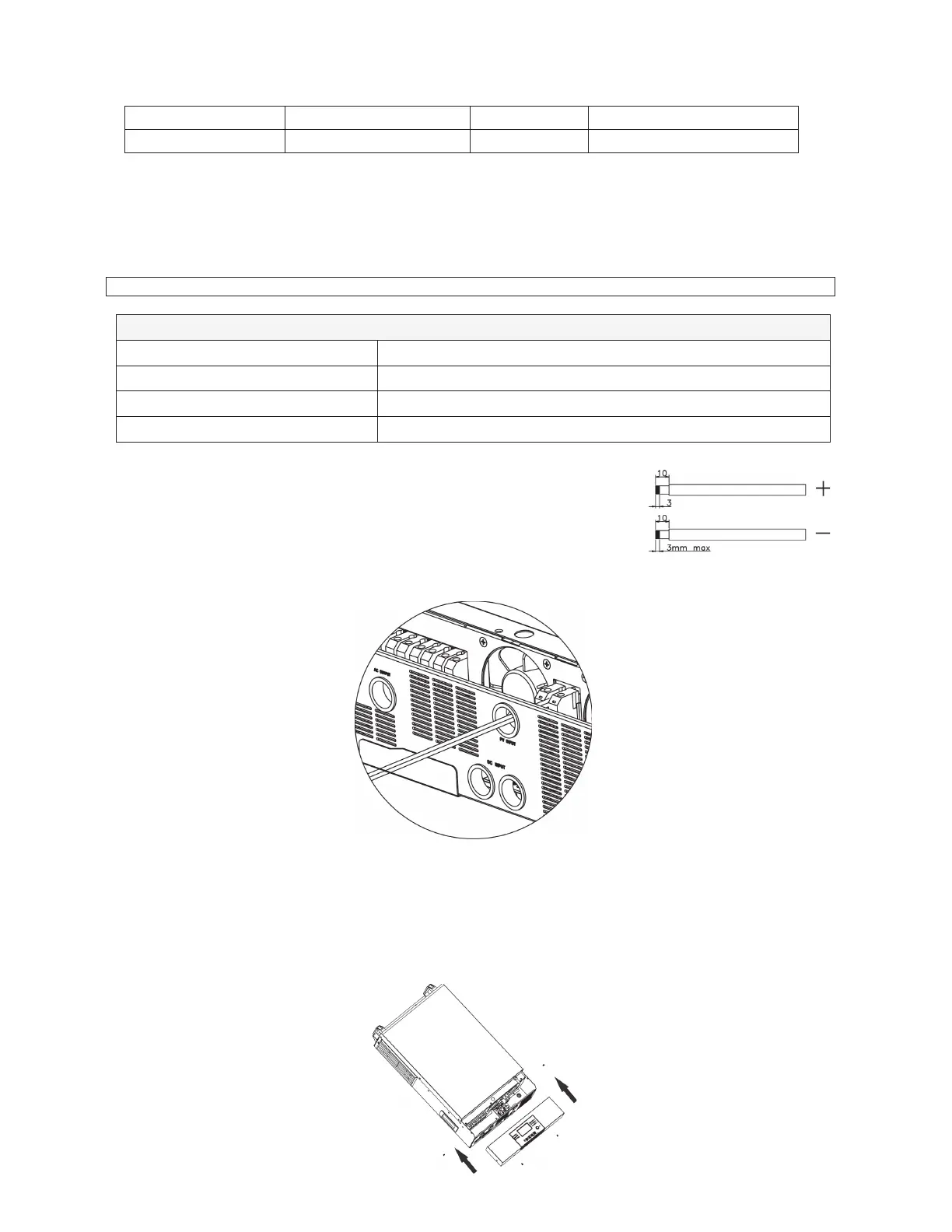
Follow the below steps to complete PV connection:
1. Remove 10 mm (3/8in) of insulation from positive and negative conductors.
2. Check for correct polarity of connections at the PV inputs at the disconnect,
with the disconnecting means off to ensure the exposed output in not live.
Connect the positive pole (+) of the PV source to the positive pole (+) of PV
input terminal. Connect the negative pole (-) of the PV source to the
negative pole (-) of the PV input terminal. Tighten the terminals.
Final Assembly
After connecting all wiring, please put the bottom cover back by screwing four screws as shown below.
7KLVFRYHULVFULWLFDOIRUVDIHXVHRIWKLVGHYLFHDV/(7+$/YROWDJHVRFFXUEHKLQGLW
11RWH Cord grips or Conduit must be used.


 To Next Page