7. FRONT PANEL CALLOUTS
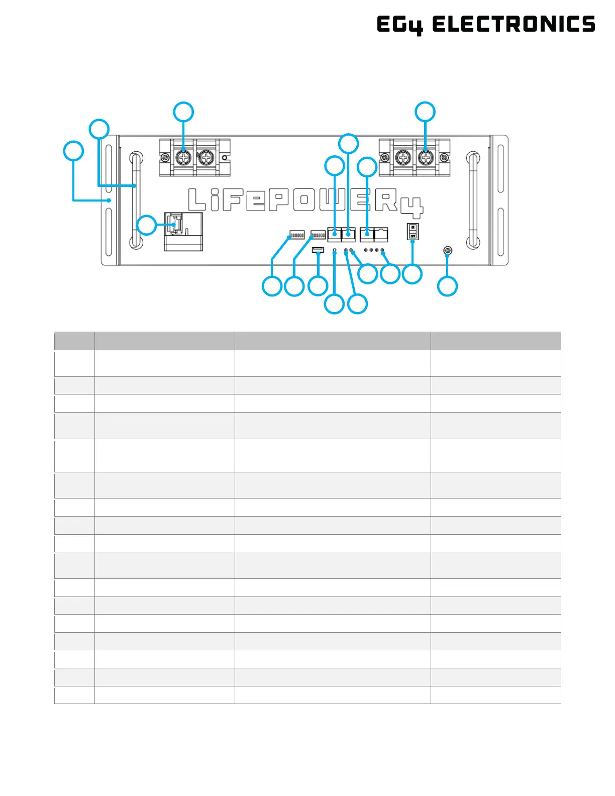
7.1 BATTERY DIAGRAM
1 Rack mount ear For battery rack mounting
Secures the battery to the
rack
For carrying/handling battery
4 CAN CAN communication interface
Pin 4 – CAN_H
Pin 5 – CAN_L
5 RS485 RS485 communication interface
Pin 1 & Pin 8 ‒ RS485_B
Pin 2 & Pin 7 – RS485_A
6 Battery Communications Parallel battery communication port
Used for closed-loop
communication
7 Negative terminal M8 bolt (x2) -
10 Battery ID DIP Switch ID for battery arrangement
6 position DIP switch, can
support 64 in parallel
15 SOC State Of Charge Display LEDs indicate charge level
Ground connection for safety
17
6
5
7
10
11
13
4
2
1
8